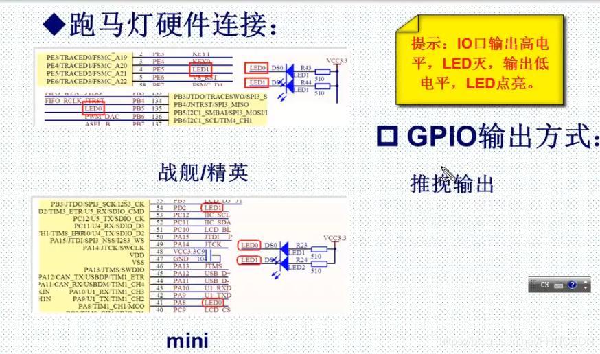
LED硬件连接:

点灯的基本步骤:

库函数版本
重要函数:

main.c部分:
#include "stm32f10x.h"
#include "LED.h"
#include "delay.h"int main(void)
{LED_Init();//GPIOB、E初始化delay_init();//延时函数初始化while(1){GPIO_SetBits(GPIOB,GPIO_Pin_5);//GPIOB.5设置输出高电平GPIO_SetBits(GPIOE,GPIO_Pin_5);//GPIOE.5设置输出高电平delay_ms(300);GPIO_ResetBits(GPIOB,GPIO_Pin_5);//GPIOB.5设置输出低电平GPIO_ResetBits(GPIOE,GPIO_Pin_5);//GPIOE.5设置输出低电平delay_ms(300);}
}
LED.c部分:
#include "LED.h"
#include "stm32f10x.h"void LED_Init(void)
{GPIO_InitTypeDef GPIO_InitLed;//定义GPIO_InitTypeDef类型的结构体RCC_APB2PeriphClockCmd(RCC_APB2Periph_GPIOB,ENABLE);//时钟使能GPIOBRCC_APB2PeriphClockCmd(RCC_APB2Periph_GPIOE,ENABLE);//时钟使能GPIOEGPIO_InitLed.GPIO_Mode=GPIO_Mode_Out_PP;GPIO_InitLed.GPIO_Pin=GPIO_Pin_5;GPIO_InitLed.GPIO_Speed=GPIO_Speed_50MHz;/*这三个是结构体内的成员,进行功能设置*/GPIO_Init(GPIOB,&GPIO_InitLed);//将定义好的结构体的地址(&GPIO_InitLed)写入GPIO_SetBits(GPIOB,GPIO_Pin_5);//设置GPIOB.5输出高电平GPIO_InitLed.GPIO_Mode=GPIO_Mode_Out_PP;GPIO_Init(GPIOE,&GPIO_InitLed);//将定义好的结构体的地址(&GPIO_InitLed)写入GPIO_SetBits(GPIOE,GPIO_Pin_5);//设置输出GPIOE.5输出高电平
}
LED.h部分:
#ifndef _LED_H
#define _LED_Hvoid LED_Init(void);#endif
寄存器版本
这一部分主要参考芯片手册进行寄存器的配置。
main.c部分:
#include "led.h"
#include "stm32f10x.h"
#include "delay.h"int main(void)
{delay_init();LED_Init();while(1){GPIOB->ODR |=1<<5;//GPIOB.5输出高电平GPIOE->ODR |=1<<5;//GPIOE.5输出高电平delay_ms(300);GPIOB->ODR &=~(1<<5);//GPIOB.5输出低电平GPIOE->ODR &=~(1<<5);//GPIOE.5输出低电平delay_ms(300);}return 0;
}
led.c部分:
#include "led.h"
#include "stm32f10x.h"void LED_Init(void)
{RCC->APB2ENR |=1<<3;//使能时钟RCC->APB2ENR |=1<<6;//使能时钟GPIOB->CRL &=0xff0fffff;//GPIOB.5的四位清0GPIOB->CRL |=0x00300000;//GPIOB.5的四位赋值0011,设置为推挽输出模式GPIOB->ODR |=1<<5;//GPIOB.5输出高电平GPIOE->CRL &=0xff0fffff;//GPIOE.5的四位清0GPIOE->CRL |=0x00300000;//GPIOE.5的四位赋值0011,设置为推挽输出模式GPIOE->ODR |=1<<5;//输出高电平
}
led.h部分:
#ifndef _LED_H
#define _LED_Hvoid LED_Init(void);#endif
位操作版本
位操作原理:

那些区域支持位操作:

位带区与位带别名区的膨胀关系图:


位带操作优越性:

映射关系:

main.c部分:
#include "led.h"
#include "delay.h"
#include "stm32f10x.h"int main(void)
{LED_Init();delay_init();while(1){PBout(5)=1;//GPIOB.5输出高电平PEout(5)=1;//GPIOE.5输出高电平delay_ms(1000);	PBout(5)=0;//GPIOB.5输出低电平PEout(5)=0;//GPIOE.5输出低电平delay_ms(1000);}	return 0;
}
void LED_Init(void)
{GPIO_InitTypeDef  GPIO_InitStructure;RCC_APB2PeriphClockCmd(RCC_APB2Periph_GPIOB|RCC_APB2Periph_GPIOE, ENABLE);GPIO_InitStructure.GPIO_Pin = GPIO_Pin_5;				GPIO_InitStructure.GPIO_Mode = GPIO_Mode_Out_PP; 		GPIO_InitStructure.GPIO_Speed = GPIO_Speed_50MHz;GPIO_Init(GPIOB, &GPIO_InitStructure);	GPIO_SetBits(GPIOB,GPIO_Pin_5);	GPIO_InitStructure.GPIO_Pin = GPIO_Pin_5;	 		GPIO_Init(GPIOE, &GPIO_InitStructure);			 GPIO_SetBits(GPIOE,GPIO_Pin_5);
}
led.h部分:
#ifndef __LED_H
#define __LED_H
#include "sys.h"
void LED_Init(void);
#endif


)


延时函数、SysTick_Config函数)

)
重映射)
 5 seconds ago)

)


