一. UFS Power Mode Change简介
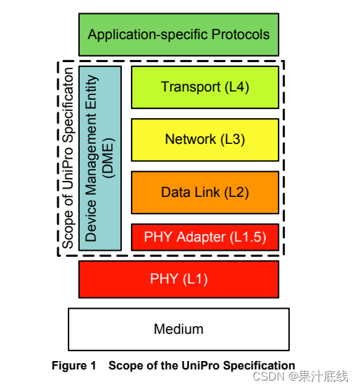
1.UFS Power Mode指的是Unipro层的Power State, 也可以称为链路(Link)上的Power Mode, 可以通过配置Unipro Attribute, 然后控制切换Unipro Power State, 当前Power Mode Change有两种触发方式:
(1) 通过DME Power Mode Change触发Power Mode Change
(2)通过DME SET PA_PWRMode[0x1571]触发Power Mode Change
目前主流的安卓平台(QCOM/MTK)使用第二种方式,先设置好本地端(Local )Local 端的Power Mode属性, 然后通过发送DME SET PA_PWRMode切换对端(Peer)的Power Mode.
UFS Power Mode相关的Unipro Attribute:
(1)PA_ACTIVETXDATALANES[0x1560]/PA_ACTIVERXDATALANES[0x1580]: Number of active Data Lanes per direction, 通过DME GET 获取对应的属性值,
(2)PA_RxGear[0x1583]/PA_TxGear[0x1568]: PWM-GEAR per direction, 默认Link Startup之后的状态就是PWM_G1
(3)PA_RxGear[0x1583]/PA_TxGear[0x1568]: HS-GEAR used per direction, 需要通过DME SET PA_PWRMode从PWM_G1切换到HS Gear1~ HS Gear4, UFS3.1最高支持HS Gear4, UFS4.0最高支持HS Gear5
(4)PA_HSSeries[0x156A]: HS RATE series (same value used for both directions)
(5)PA_TxTermination[0x1569]/PA_RxTermination[0x1584]: Line termination per direction
(6)PA_PWRMode[0x1571]: Power Mode for each direction combined into a single PA_PWRMode Attribute, 安卓UFS驱动就是通过DME SET PA_PWRMode触发Peer端Power Mode Change流程

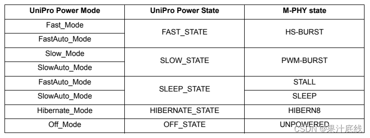
UniPro Power Modes:
| Power Mode | Description | UniPro Power State |
| Fast_Mode | The Fast_Mode is capable of the highest data transmission rate of all Power Modes. The Link is always ready to send and receive data while providing a well-defined latency, which is the lowest of any UniPro Power Modes. The actual data rate per Data Lane in the Fast_Mode is PHY-specific. | FAST_STATE |
| Slow_Mode | The Slow_Mode is also capable of transmitting data. It should be less than, or equal to, the data rate in Fast_Mode and consume less, or equal, power. The provided latency is welldefined but might be higher than in the Fast_Mode. The actual data rate in the Slow_Mode is PHY-specific. | SLOW_STATE |
| FastAuto_Mode | The FastAuto_Mode allows the UniPro stack to autonomously switch between the FAST_STATE and the SLEEP_STATE, depending whether or not the DL Layer has data to send. By switching between states, the FastAuto_Mode might save power compared to the Fast_Mode, but at the cost of a possibly less well-defined latency. UniPro does not dictate a certain method for the autonomous switching. In any case, a PA Layer shall be able to transmit DL Layer data when in FastAuto_Mode. | FAST_STATE, SLEEP_STATE |
| SlowAuto_Mode | The SlowAuto_Mode allows the UniPro stack to autonomously switch between the SLOW_STATE and the SLEEP_STATE, depending on whether or not the DL Layer has data to send. By switching between states, the SlowAuto_Mode might save power compared to the Slow_Mode, but at the cost of a possibly less well-defined latency. UniPro does not dictate a certain method for the autonomous switching. In case a UniPro stack does not provide any method for autonomous switching, its SlowAuto_Mode shall be strictly mapped to the SLOW_STATE. In any case, a PA Layer shall be able to transmit DL Layer data when in SlowAuto_Mode | SLOW_STATE, SLEEP_STATE |
| Hibernate_Mode | The Hibernate_Mode is a low Power Mode in which no data transmission is possible. There may be a long latency returning from this mode to one of the other modes. The Hibernate_Mode should consume less power than any of the other modes in this table, except Off_Mode. | HIBERNATE_STATE |
| Off_Mode | The Off_Mode prepares for the removal of power. When a Device is ready to have its power removed it enters the OFF_STATE | OFF_STATE\ |
Unipro Power State to M-PHY state Mapping:

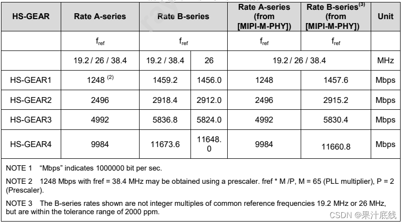
HS Gear Rates:UFS3.1最高支持HS Gear4, RateB,

二. UFS Power Mode Change概述

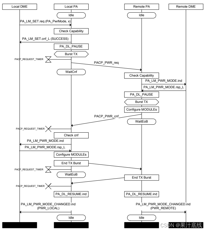
Power Mode Change using PACP_PWR_req and PACP_PWR_cnf流程:
(1) UFS Host侧(通常是UFS Host Driver)通过HCI发送DME SET PA_PWRMode[0x1571]原语到本端的PA层,
(2)本地Local端会检查Capability, 检查合适之后发送回复给本地的Host侧的 PA_PWRMode 原语,
(3)PA层启动TX链路,并且发送PACP_PWR_req(Power Mode change request)给远端(Remote)侧的PA层,
(4)远端(Remote)侧的PA层会检查Capability, 检查合适之后发送PA_LM_PWR_MODE.ind通知远端进行Power Mode Change,
(5)远端收到之后,会回复PA_LM_PWR_MODE.rsp_L,表示收到Power Mode Change请求
(6)远端启动TX, 并且发送PACP_PWR_cnf用来回复本地Local端的PACP_PWR_req请求
(7)本地端收到PACP_PWR_cnf后,检查合适之后发送PA_LM_PWR_MODE.ind通知本地端进行Power Mode Change,
(8)本地端收到之后,会回复PA_LM_PWR_MODE.rsp_L,表示收到Power Mode Change请求
(9)本地端关闭TX活动,远端关闭TX活动
(10)本地端发送PA_DL_RESUME.ind唤醒Data Link Layer,远端发送PA_DL_RESUME.ind唤醒Data Link Layer
(11)本地端发送PA_LM_PWR_MODE_CHANGED.ind (PWR_LOCAL)回复Power Mode Change的结果给本地端DME层
(12)远端PA层通过发送PA_LM_PWR_MODE_CHANGED.ind(PWR_REMOTE)回复Power Mode Change的结果给本地端DME层
Note1: PA 层之间(Local PA层和Remote PA层)的通信需要使用协议定义PA Control Protocol (PACP)数据包。
Note2: 可以通过PA协议分析仪抓取PA数据包,分析Power Mode Change的流程,PA协议分析仪抓取的数据是Local PA和Remote PA之间的数据。
三. UFS Power Mode Change详解
1. 安卓系统的Power Mode Change:
(1). 在安卓系统上,UFS初始化LinkStartup之后的Power Mode是PWM Gear1, Slow_Mode,RateA, Lane1,
(2). 获取最大的HSGEAR,获取PA的Connect Data Lane,通过DME Get获取对应的值
(3). 进行Power Mode Change, 切换完之后的Power Mode是HS Gear4, FastMode, RateB, Lane2.
2. Power Mode Change失败遇到的问题:
(1). UFS Host侧的Reference clock和UFS Device侧的bRefClkFreq Attribute不匹配,切换失败,可以使用可以使用UFS协议分析仪或者ufs utils调试
(2). UFS切高速的时候没有设置adapt, 目前HS Gear4及以上需要进行设置adapt, 用来做数据传输的时序训练,保证链路层数据传输的稳定性,可以使用UFS协议分析仪调试
(3) UFS Device侧没有进行LinkStartup或者Link Down,可以使用UFS协议分析仪调试
(4) UFS 相关的Vcc/Vccq/Vccq2异常,可以使用万用表或者示波器调试
(5) UFS 状态异常,可能需要重新刷UFS FW恢复, 可以通过FFU升级UFS FW
3. Power Mode Change省电:
(1). 安卓系统侧在省电的时候,会把UFS Power Mode切换为HS Gear1, FastMode, RateB, Lane2
(2) UFS Device侧在省电的时候,会关闭Vcc, Link 进入Hibernate状态,UFS Device进入省电模式
(3) UFS Device侧在省电的时候,会将UFS Cache的数据刷到UFS Nand存储介质
四. UFS Power Mode Change代码实现
1. 获取UFS Device支持的最大Power Mode, 需要通过DME GET命令读取连接的Lane Count, 最大的HS Gear, 调试的时候可以通过UFS Event Trace分析流程
/*** ufshcd_get_max_pwr_mode - reads the max power mode negotiated with device* @hba: per-adapter instance*/
static int ufshcd_get_max_pwr_mode(struct ufs_hba *hba)
{struct ufs_pa_layer_attr *pwr_info = &hba->max_pwr_info.info;if (hba->max_pwr_info.is_valid)return 0;pwr_info->pwr_tx = FAST_MODE;pwr_info->pwr_rx = FAST_MODE;pwr_info->hs_rate = PA_HS_MODE_B;/* Get the connected lane count */ufshcd_dme_get(hba, UIC_ARG_MIB(PA_CONNECTEDRXDATALANES),&pwr_info->lane_rx);ufshcd_dme_get(hba, UIC_ARG_MIB(PA_CONNECTEDTXDATALANES),&pwr_info->lane_tx);if (!pwr_info->lane_rx || !pwr_info->lane_tx) {dev_err(hba->dev, "%s: invalid connected lanes value. rx=%d, tx=%d\n",__func__,pwr_info->lane_rx,pwr_info->lane_tx);return -EINVAL;}/** First, get the maximum gears of HS speed.* If a zero value, it means there is no HSGEAR capability.* Then, get the maximum gears of PWM speed.*/ufshcd_dme_get(hba, UIC_ARG_MIB(PA_MAXRXHSGEAR), &pwr_info->gear_rx);if (!pwr_info->gear_rx) {ufshcd_dme_get(hba, UIC_ARG_MIB(PA_MAXRXPWMGEAR),&pwr_info->gear_rx);if (!pwr_info->gear_rx) {dev_err(hba->dev, "%s: invalid max pwm rx gear read = %d\n",__func__, pwr_info->gear_rx);return -EINVAL;}pwr_info->pwr_rx = SLOW_MODE;}ufshcd_dme_peer_get(hba, UIC_ARG_MIB(PA_MAXRXHSGEAR),&pwr_info->gear_tx);if (!pwr_info->gear_tx) {ufshcd_dme_peer_get(hba, UIC_ARG_MIB(PA_MAXRXPWMGEAR),&pwr_info->gear_tx);if (!pwr_info->gear_tx) {dev_err(hba->dev, "%s: invalid max pwm tx gear read = %d\n",__func__, pwr_info->gear_tx);return -EINVAL;}pwr_info->pwr_tx = SLOW_MODE;}hba->max_pwr_info.is_valid = true;return 0;
}
2. 配置UFS Device新的Power Mode, 主要分为两步,第一步是获取并配置UFS Host侧Power Mode信息,第二步是切换Power Mode,
/*** ufshcd_config_pwr_mode - configure a new power mode* @hba: per-adapter instance* @desired_pwr_mode: desired power configuration*/
int ufshcd_config_pwr_mode(struct ufs_hba *hba,struct ufs_pa_layer_attr *desired_pwr_mode)
{struct ufs_pa_layer_attr final_params = { 0 };int ret;ret = ufshcd_vops_pwr_change_notify(hba, PRE_CHANGE,desired_pwr_mode, &final_params);if (ret)memcpy(&final_params, desired_pwr_mode, sizeof(final_params));ret = ufshcd_change_power_mode(hba, &final_params);if (!ret)ufshcd_print_pwr_info(hba);return ret;
}
EXPORT_SYMBOL_GPL(ufshcd_config_pwr_mode);
(1) 获取UFS Host侧的Power Mode能力信息,包括支持的HS Gear, 使能Data Lane,
static int ufs_qcom_pwr_change_notify(struct ufs_hba *hba,enum ufs_notify_change_status status,struct ufs_pa_layer_attr *dev_max_params,struct ufs_pa_layer_attr *dev_req_params)
{u32 val;struct ufs_qcom_host *host = ufshcd_get_variant(hba);struct phy *phy = host->generic_phy;struct ufs_qcom_dev_params ufs_qcom_cap;int ret = 0;int res = 0;if (!dev_req_params) {pr_err("%s: incoming dev_req_params is NULL\n", __func__);ret = -EINVAL;goto out;}switch (status) {case PRE_CHANGE:ufs_qcom_cap.tx_lanes = UFS_QCOM_LIMIT_NUM_LANES_TX;ufs_qcom_cap.rx_lanes = UFS_QCOM_LIMIT_NUM_LANES_RX;ufs_qcom_cap.hs_rx_gear = UFS_QCOM_LIMIT_HSGEAR_RX;ufs_qcom_cap.hs_tx_gear = UFS_QCOM_LIMIT_HSGEAR_TX;ufs_qcom_cap.pwm_rx_gear = UFS_QCOM_LIMIT_PWMGEAR_RX;ufs_qcom_cap.pwm_tx_gear = UFS_QCOM_LIMIT_PWMGEAR_TX;ufs_qcom_cap.rx_pwr_pwm = UFS_QCOM_LIMIT_RX_PWR_PWM;ufs_qcom_cap.tx_pwr_pwm = UFS_QCOM_LIMIT_TX_PWR_PWM;ufs_qcom_cap.rx_pwr_hs = UFS_QCOM_LIMIT_RX_PWR_HS;ufs_qcom_cap.tx_pwr_hs = UFS_QCOM_LIMIT_TX_PWR_HS;ufs_qcom_cap.hs_rate = UFS_QCOM_LIMIT_HS_RATE;ufs_qcom_cap.desired_working_mode =UFS_QCOM_LIMIT_DESIRED_MODE;if (host->hw_ver.major == 0x1) {/** HS-G3 operations may not reliably work on legacy QCOM* UFS host controller hardware even though capability* exchange during link startup phase may end up* negotiating maximum supported gear as G3.* Hence downgrade the maximum supported gear to HS-G2.*/if (ufs_qcom_cap.hs_tx_gear > UFS_HS_G2)ufs_qcom_cap.hs_tx_gear = UFS_HS_G2;if (ufs_qcom_cap.hs_rx_gear > UFS_HS_G2)ufs_qcom_cap.hs_rx_gear = UFS_HS_G2;}ret = ufs_qcom_get_pwr_dev_param(&ufs_qcom_cap,dev_max_params,dev_req_params);if (ret) {pr_err("%s: failed to determine capabilities\n",__func__);goto out;}/* enable the device ref clock before changing to HS mode */if (!ufshcd_is_hs_mode(&hba->pwr_info) &&ufshcd_is_hs_mode(dev_req_params))ufs_qcom_dev_ref_clk_ctrl(host, true);break;case POST_CHANGE:if (ufs_qcom_cfg_timers(hba, dev_req_params->gear_rx,dev_req_params->pwr_rx,dev_req_params->hs_rate, false)) {dev_err(hba->dev, "%s: ufs_qcom_cfg_timers() failed\n",__func__);/** we return error code at the end of the routine,* but continue to configure UFS_PHY_TX_LANE_ENABLE* and bus voting as usual*/ret = -EINVAL;}val = ~(MAX_U32 << dev_req_params->lane_tx);res = ufs_qcom_phy_set_tx_lane_enable(phy, val);if (res) {dev_err(hba->dev, "%s: ufs_qcom_phy_set_tx_lane_enable() failed res = %d\n",__func__, res);ret = res;}/* cache the power mode parameters to use internally */memcpy(&host->dev_req_params,dev_req_params, sizeof(*dev_req_params));ufs_qcom_update_bus_bw_vote(host);/* disable the device ref clock if entered PWM mode */if (ufshcd_is_hs_mode(&hba->pwr_info) &&!ufshcd_is_hs_mode(dev_req_params))ufs_qcom_dev_ref_clk_ctrl(host, false);break;default:ret = -EINVAL;break;}
out:return ret;
}
(2)通过DME SET配置Local PA侧(UFS Host PA侧)的Power Mode信息,包括Hs Gear, TERMINATION, HSSERIES, ACTIVETXDATALANES,
static int ufshcd_change_power_mode(struct ufs_hba *hba,struct ufs_pa_layer_attr *pwr_mode)
{int ret;/* if already configured to the requested pwr_mode */if (pwr_mode->gear_rx == hba->pwr_info.gear_rx &&pwr_mode->gear_tx == hba->pwr_info.gear_tx &&pwr_mode->lane_rx == hba->pwr_info.lane_rx &&pwr_mode->lane_tx == hba->pwr_info.lane_tx &&pwr_mode->pwr_rx == hba->pwr_info.pwr_rx &&pwr_mode->pwr_tx == hba->pwr_info.pwr_tx &&pwr_mode->hs_rate == hba->pwr_info.hs_rate) {dev_dbg(hba->dev, "%s: power already configured\n", __func__);return 0;}/** Configure attributes for power mode change with below.* - PA_RXGEAR, PA_ACTIVERXDATALANES, PA_RXTERMINATION,* - PA_TXGEAR, PA_ACTIVETXDATALANES, PA_TXTERMINATION,* - PA_HSSERIES*/ufshcd_dme_set(hba, UIC_ARG_MIB(PA_RXGEAR), pwr_mode->gear_rx);ufshcd_dme_set(hba, UIC_ARG_MIB(PA_ACTIVERXDATALANES),pwr_mode->lane_rx);if (pwr_mode->pwr_rx == FASTAUTO_MODE ||pwr_mode->pwr_rx == FAST_MODE)ufshcd_dme_set(hba, UIC_ARG_MIB(PA_RXTERMINATION), TRUE);elseufshcd_dme_set(hba, UIC_ARG_MIB(PA_RXTERMINATION), FALSE);ufshcd_dme_set(hba, UIC_ARG_MIB(PA_TXGEAR), pwr_mode->gear_tx);ufshcd_dme_set(hba, UIC_ARG_MIB(PA_ACTIVETXDATALANES),pwr_mode->lane_tx);if (pwr_mode->pwr_tx == FASTAUTO_MODE ||pwr_mode->pwr_tx == FAST_MODE)ufshcd_dme_set(hba, UIC_ARG_MIB(PA_TXTERMINATION), TRUE);elseufshcd_dme_set(hba, UIC_ARG_MIB(PA_TXTERMINATION), FALSE);if (pwr_mode->pwr_rx == FASTAUTO_MODE ||pwr_mode->pwr_tx == FASTAUTO_MODE ||pwr_mode->pwr_rx == FAST_MODE ||pwr_mode->pwr_tx == FAST_MODE)ufshcd_dme_set(hba, UIC_ARG_MIB(PA_HSSERIES),pwr_mode->hs_rate);ret = ufshcd_uic_change_pwr_mode(hba, pwr_mode->pwr_rx << 4| pwr_mode->pwr_tx);if (ret) {dev_err(hba->dev,"%s: power mode change failed %d\n", __func__, ret);} else {ufshcd_vops_pwr_change_notify(hba, POST_CHANGE, NULL,pwr_mode);memcpy(&hba->pwr_info, pwr_mode,sizeof(struct ufs_pa_layer_attr));}return ret;
}
3. 通过发送DME SET PA_PWRMODE(0x0x1571)触发Remote PA侧(UFS Device PA侧)进行Power Mode Change.
#define PA_PWRMODE		0x1571/*** ufshcd_uic_change_pwr_mode - Perform the UIC power mode chage*				using DME_SET primitives.* @hba: per adapter instance* @mode: powr mode value** Returns 0 on success, non-zero value on failure*/
static int ufshcd_uic_change_pwr_mode(struct ufs_hba *hba, u8 mode)
{struct uic_command uic_cmd = {0};int ret;if (hba->quirks & UFSHCD_QUIRK_BROKEN_PA_RXHSUNTERMCAP) {ret = ufshcd_dme_set(hba,UIC_ARG_MIB_SEL(PA_RXHSUNTERMCAP, 0), 1);if (ret) {dev_err(hba->dev, "%s: failed to enable PA_RXHSUNTERMCAP ret %d\n",__func__, ret);goto out;}}uic_cmd.command = UIC_CMD_DME_SET;uic_cmd.argument1 = UIC_ARG_MIB(PA_PWRMODE);uic_cmd.argument3 = mode;ufshcd_hold(hba, false);ret = ufshcd_uic_pwr_ctrl(hba, &uic_cmd);ufshcd_release(hba);out:return ret;
}
五. 参考资料
1. UniPro v1.6 Specification
2. JESD220E Universal Flash Storage (UFS) Version 3.1
3. Linux Kernel 4.19 Source Code


)
使用OpenCompass进行模型评估)


