目录
CG1-v1.0-点和直线的绘制
第1关:OpenGL点的绘制
第2关:OpenGL简单图形绘制
第3关:OpenGL直线绘制
第4关:0<1直线绘制-dda算法<>
第5关:0<1直线绘制-中点算法<>
第6关:一般直线绘制
CG1-v2.0-直线绘制
第1关:直线光栅化-DDA画线算法
第2关:直线光栅化-中点画线算法
第3关:直线光栅化-Bresenham画线算法
第4关:直线光栅化-任意斜率的Bresenham画线算法
CG2-v2.0-三角形填充
第1关:扫描线填充法
第2关:重心坐标填充法
第3关:同侧判断填充法
直线裁剪v1.0
第1关:Cohen-Sutherland编码裁剪算法
第2关:中点分割裁剪算法
第3关:Liang-Barsky参数化裁剪算法
CG2-v1.0-二维几何变换
第1关:正方形的平移与缩放
第2关:正方形的平移和旋转
第3关:正方形的变换组合
第4关:三菱形状
CG3-v2.0-图形几何变换
第1关:平移、缩放、旋转正方体
第2关:图形的平移与缩放
第3关:图形的平移与旋转
第4关:图形的旋转与缩放
第5关:绘制三菱形状
模型、观察及视口变换v1.0
第1关:立方体模型变换
第2关:立方体观察变换
第3关:立方体视口变换
模型、观察及视口变换v2.0
第1关:模型变换-左右两个立方体
第2关:观察变换
第3关:视口变换
投影变换v1.0
第1关:立方体透视投影
第2关:立方体平行投影
投影变换v2.0
第1关:一点透视
第2关:两点透视
第3关:三视图与正等测投影
第4关:视口变换与三视图
CG1-v1.0-点和直线的绘制
第1关:OpenGL点的绘制
一. 任务描述
根据下面要求,在右侧修改代码,绘制出预期输出的图片。平台会对你编写的代码进行测试。
1.本关任务
熟悉编程环境; 了解光栅图形显示器的特点; 了解计算机绘图的特点; 进行编程,以OpenGL为开发平台设计程序,以能够在屏幕上生成三个坐标、颜色和尺寸一定的点。
2.预期输出
3.具体要求
(1) 背景色为黑色,用 glClearColor()来完成;
(2) 渲染的点的直径设置为 3;
(3) 选用 GL_POINTS 作为图形类型;
(4) 三个点的颜色分别为(1.0f, 0.0f, 0.0f), (0.0f,1.0f,0.0f), (0.0f,0.0f,1.0f);
(5) 三个点对应的顶点坐标分别为(-0.4f,-0.4f), (0.0f,0.0f), (0.4f,0.4f)。

// 提示:写完代码请保存之后再进行评测
#include <GL/freeglut.h>
#include<stdio.h>// 评测代码所用头文件-开始
#include<opencv2/core/core.hpp>
#include<opencv2/highgui/highgui.hpp>
#include<opencv2/imgproc/imgproc.hpp>
// 评测代码所用头文件-结束void myDisplay(void)
{// 请在此添加你的代码/********** Begin ********/glClearColor(0.0,0.0,0.0,0.0);glPointSize(3);glBegin(GL_POINTS);glColor3f(1.0,0.0,0.0);glVertex2f(-0.4,-0.4);glColor3f(0.0,1.0,0.0);glVertex2f(0.0,0.0);glColor3f(0.0,0.0,1.0);glVertex2f(0.4,0.4);glEnd();/********** End **********/glFlush();
}int main(int argc, char *argv[])
{glutInit(&argc, argv);glutInitWindowPosition(100, 100);glutInitWindowSize(400, 400);glutCreateWindow("Hello Point!");glutDisplayFunc(&myDisplay);glutMainLoopEvent();     /*************以下为评测代码,与本次实验内容无关,请勿修改**************/GLubyte* pPixelData = (GLubyte*)malloc(400 * 400 * 3);//分配内存GLint viewport[4] = {0};    glReadBuffer(GL_FRONT);glPixelStorei(GL_UNPACK_ALIGNMENT, 4);glGetIntegerv(GL_VIEWPORT, viewport);glReadPixels(viewport[0], viewport[1], viewport[2], viewport[3], GL_RGB, GL_UNSIGNED_BYTE, pPixelData);cv::Mat img;std::vector<cv::Mat> imgPlanes;img.create(400, 400, CV_8UC3);cv::split(img, imgPlanes);for(int i = 0; i < 400; i ++) {unsigned char* plane0Ptr = imgPlanes[0].ptr<unsigned char>(i);unsigned char* plane1Ptr = imgPlanes[1].ptr<unsigned char>(i);unsigned char* plane2Ptr = imgPlanes[2].ptr<unsigned char>(i);for(int j = 0; j < 400; j ++) {int k = 3 * (i * 400 + j);plane2Ptr[j] = pPixelData[k];plane1Ptr[j] = pPixelData[k+1];plane0Ptr[j] = pPixelData[k+2];}}cv::merge(imgPlanes, img);cv::flip(img, img ,0); cv::namedWindow("openglGrab");cv::imshow("openglGrab", img);//cv::waitKey();cv::imwrite("../img_step1/test.jpg", img);return 0;
}
第2关:OpenGL简单图形绘制
一.任务描述
根据下面要求,在右侧修改代码,绘制出预期输出的图片。平台会对你编写的代码进行测试。
1.本关任务
利用 OpenGL 作为开发平台设计程序,生成一个光栅图。
2.预期输出
3.具体要求
(1).使用黑色作为背景,采用 glClearColor 来实现;
(2).绘制一个矩形,颜色为(1.0f,1.0f,1.0f),矩阵位置(-0.5f,-0.5f,0.5f,0.5f);
(3).绘制一个三角形,三个顶点颜色分别为(1.0f, 0.0f, 0.0f), (0.0f,1.0f,0.0f), (0.0f,0.0f,1.0f),对应的顶点坐标分别为(0.0f,1.0f), (0.8f,-0.5f), (-0.8f,-0.5f);
(4).绘制三个直径为3的点,颜色为(1.0f, 0.0f, 0.0f), (0.0f,1.0f,0.0f), (0.0f,0.0f,1.0f),对应的顶点坐标分别为(-0.4f,-0.4f), (0.0f,0.0f),(0.4f,0.4f)。

// 提示:写完代码请保存之后再进行评测
#include <GL/freeglut.h>
#include<stdio.h>// 评测代码所用头文件-开始
#include<opencv2/core/core.hpp>
#include<opencv2/highgui/highgui.hpp>
#include<opencv2/imgproc/imgproc.hpp>
// 评测代码所用头文件-结束void myDisplay(void)
{// 请在此添加你的代码/********** Begin ********/glClearColor(0.0,0.0,0.0,0.0);glColor3f(1.0,1.0,1.0);glRectf(-0.5,-0.5,0.5,0.5);glBegin(GL_TRIANGLES);glColor3f(1.0,0.0,0.0);glVertex2f(0.0,1.0);glColor3f(0.0,1.0,0.0);glVertex2f(0.8,-0.5);glColor3f(0.0,0.0,1.0);glVertex2f(-0.8,-0.5);glEnd();glPointSize(3);glBegin(GL_POINTS);glColor3f(1.0,0.0,0.0);glVertex2f(-0.4,-0.4);glColor3f(0.0,1.0,0.0);glVertex2f(0.0,0.0);glColor3f(0.0,0.0,1.0);glVertex2f(0.4,0.4);glEnd();/********** End **********/glFlush();
}int main(int argc, char *argv[])
{glutInit(&argc, argv);glutInitWindowPosition(100, 100);glutInitWindowSize(400, 400);glutCreateWindow("Hello Point!");glutDisplayFunc(&myDisplay);glutMainLoopEvent();     /*************以下为评测代码,与本次实验内容无关,请勿修改**************/GLubyte* pPixelData = (GLubyte*)malloc(400 * 400 * 3);//分配内存GLint viewport[4] = {0};    glReadBuffer(GL_FRONT);glPixelStorei(GL_UNPACK_ALIGNMENT, 4);glGetIntegerv(GL_VIEWPORT, viewport);glReadPixels(viewport[0], viewport[1], viewport[2], viewport[3], GL_RGB, GL_UNSIGNED_BYTE, pPixelData);cv::Mat img;std::vector<cv::Mat> imgPlanes;img.create(400, 400, CV_8UC3);cv::split(img, imgPlanes);for(int i = 0; i < 400; i ++) {unsigned char* plane0Ptr = imgPlanes[0].ptr<unsigned char>(i);unsigned char* plane1Ptr = imgPlanes[1].ptr<unsigned char>(i);unsigned char* plane2Ptr = imgPlanes[2].ptr<unsigned char>(i);for(int j = 0; j < 400; j ++) {int k = 3 * (i * 400 + j);plane2Ptr[j] = pPixelData[k];plane1Ptr[j] = pPixelData[k+1];plane0Ptr[j] = pPixelData[k+2];}}cv::merge(imgPlanes, img);cv::flip(img, img ,0); cv::namedWindow("openglGrab");cv::imshow("openglGrab", img);//cv::waitKey();cv::imwrite("../img_step2/test.jpg", img);return 0;
}
第3关:OpenGL直线绘制
一.任务描述
根据下面要求,在右侧修改代码,绘制出预期输出的图片。平台会对你编写的代码进行测试。
1.本关任务
理解基本图形元素光栅化的基本原理; 了解和使用OpenGL的生成直线的命令,来验证程序运行结果。
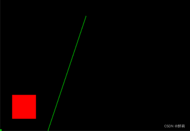
2.预期输出
3.具体要求
(1).背景色为黑色,用 glclearcolor 来完成;
(2).绘制一个矩形,颜色为(1.0f,0.0f,0.0f),矩形位置(25.0,25.0,75.0,75.0);
(3).绘制一个直径为10的点,颜色为(0.0f, 1.0f, 0.0f),对应的点坐标为原点;
(4).利用GL_LINES的绘线方式绘制一条线,其中线段的两个顶点颜色分别为(0.0f, 1.0f, 0.0f),(0.0f, 1.0f, 0.0f)两个顶点的坐标分别为(100.0f, 0.0f),(180.0f, 240.0f);
5.调用向glutReshapeFunC注册的函数。
// 提示:写完代码请保存之后再进行评测
#include <GL/freeglut.h>
#include<stdio.h>// 评测代码所用头文件-开始
#include<opencv2/core/core.hpp>
#include<opencv2/highgui/highgui.hpp>
#include<opencv2/imgproc/imgproc.hpp>
// 评测代码所用头文件-结束void myDisplay(void)
{// 请在此添加你的代码/********** Begin ********/glClearColor(0.0,0.0,0.0,0.0);glColor3f(1.0,0.0f,0.0f);glRectf(25.0,25.0,75.0,75.0);glPointSize(10);glBegin(GL_POINTS);glColor3f(0.0f,1.0f,0.0f);glVertex2f(0.0f,0.0f);glEnd();glBegin(GL_LINES);glColor3f(0.0f,1.0f,0.0f);glVertex2f(100.0f,0.0f);glColor3f(0.0f,1.0f,0.0f);glVertex2f(180.0f,240.0f);glEnd();/********** End **********/glFlush();
}
void Init()
{glClearColor(0.0, 0.0, 0.0, 0.0);glShadeModel(GL_SMOOTH);
}
void myReshape(int w, int h)
{glViewport(0, 0, (GLsizei)w, (GLsizei)h);glMatrixMode(GL_PROJECTION);glLoadIdentity();gluOrtho2D(0.0, (GLdouble)w, 0.0, (GLdouble)h);
}int main(int argc, char *argv[])
{glutInit(&argc, argv);glutInitWindowPosition(100, 100);glutInitWindowSize(400, 400);glutCreateWindow("Hello Point!");Init();glutDisplayFunc(myDisplay);glutReshapeFunc(myReshape);glutMainLoopEvent();     /*************以下为评测代码,与本次实验内容无关,请勿修改**************/GLubyte* pPixelData = (GLubyte*)malloc(400 * 400 * 3);//分配内存GLint viewport[4] = {0};    glReadBuffer(GL_FRONT);glPixelStorei(GL_UNPACK_ALIGNMENT, 4);glGetIntegerv(GL_VIEWPORT, viewport);glReadPixels(viewport[0], viewport[1], viewport[2], viewport[3], GL_RGB, GL_UNSIGNED_BYTE, pPixelData);cv::Mat img;std::vector<cv::Mat> imgPlanes;img.create(400, 400, CV_8UC3);cv::split(img, imgPlanes);for(int i = 0; i < 400; i ++) {unsigned char* plane0Ptr = imgPlanes[0].ptr<unsigned char>(i);unsigned char* plane1Ptr = imgPlanes[1].ptr<unsigned char>(i);unsigned char* plane2Ptr = imgPlanes[2].ptr<unsigned char>(i);for(int j = 0; j < 400; j ++) {int k = 3 * (i * 400 + j);plane2Ptr[j] = pPixelData[k];plane1Ptr[j] = pPixelData[k+1];plane0Ptr[j] = pPixelData[k+2];}}cv::merge(imgPlanes, img);cv::flip(img, img ,0); cv::namedWindow("openglGrab");cv::imshow("openglGrab", img);//cv::waitKey();cv::imwrite("../img_step3/test.jpg", img);return 0;
}
第4关:0<k<1直线绘制-DDA算法
一.任务描述
根据下面要求,在右侧修改代码,绘制出预期输出的图片。平台会对你编写的代码进行测试。
1.本关任务
掌握一种基本图形元素光栅化算法,利用OpenGL实现直线光栅化的DDA算法。
2.预期输出
3.具体要求
(1).背景色为黑色,用 glclearcolor 来完成;
(2).利用DDA算法生成一条直线,线粗为1,直线颜色为(1.0f,1.0f,0.0f),直线两端点坐标为(0,0,200,200)。

// 提示:写完代码请保存之后再进行评测
#include <GL/freeglut.h>
#include<stdio.h>// 评测代码所用头文件-开始
#include<opencv2/core/core.hpp>
#include<opencv2/highgui/highgui.hpp>
#include<opencv2/imgproc/imgproc.hpp>
// 评测代码所用头文件-结束void LineDDA(int x0, int y0, int x1, int y1)
{// 请在此添加你的代码/********** Begin ********/int x;int dy, dx;int y;float k;dx = x1 - x0, dy = y1 - y0;k = dy / dx;y = y0;glColor3f(1.0f, 1.0f, 0.0f);glPointSize(1);for (x = x0; x <= x1; x++){glBegin(GL_POINTS);glVertex2i(x, (int)(y + 0.5)); glEnd();y += k;}/********** End **********/glFlush();
}void myDisplay(void)
{// 请在此添加你的代码/********** Begin ********/
glClearColor(0.0, 0.0, 0.0, 0.0);LineDDA( 0, 0, 200, 200);/********** End **********/glFlush();
}
void Init()
{glClearColor(0.0, 0.0, 0.0, 0.0);glShadeModel(GL_SMOOTH);
}
void myReshape(int w, int h)
{glViewport(0, 0, (GLsizei)w, (GLsizei)h);glMatrixMode(GL_PROJECTION);glLoadIdentity();gluOrtho2D(0.0, (GLdouble)w, 0.0, (GLdouble)h);
}int main(int argc, char *argv[])
{glutInit(&argc, argv);glutInitWindowPosition(100, 100);glutInitWindowSize(400, 400);glutCreateWindow("Hello Point!");Init();glutDisplayFunc(myDisplay);glutReshapeFunc(myReshape);glutMainLoopEvent();     /*************以下为评测代码,与本次实验内容无关,请勿修改**************/GLubyte* pPixelData = (GLubyte*)malloc(400 * 400 * 3);//分配内存GLint viewport[4] = {0};glReadBuffer(GL_FRONT);glPixelStorei(GL_UNPACK_ALIGNMENT, 4);glGetIntegerv(GL_VIEWPORT, viewport);glReadPixels(viewport[0], viewport[1], viewport[2], viewport[3], GL_RGB, GL_UNSIGNED_BYTE, pPixelData);cv::Mat img;std::vector<cv::Mat> imgPlanes;img.create(400, 400, CV_8UC3);cv::split(img, imgPlanes);for(int i = 0; i < 400; i ++) {unsigned char* plane0Ptr = imgPlanes[0].ptr<unsigned char>(i);unsigned char* plane1Ptr = imgPlanes[1].ptr<unsigned char>(i);unsigned char* plane2Ptr = imgPlanes[2].ptr<unsigned char>(i);for(int j = 0; j < 400; j ++) {int k = 3 * (i * 400 + j);plane2Ptr[j] = pPixelData[k];plane1Ptr[j] = pPixelData[k+1];plane0Ptr[j] = pPixelData[k+2];}}cv::merge(imgPlanes, img);cv::flip(img, img ,0); cv::namedWindow("openglGrab");cv::imshow("openglGrab", img);//cv::waitKey();cv::imwrite("../img_step4/test.jpg", img);return 0;
}
第5关:0<k<1直线绘制-中点算法
一.任务描述
根据下面要求,在右侧修改代码,绘制出预期输出的图片。平台会对你编写的代码进行测试。
1.本关任务
掌握一种基本图形元素光栅化算法,利用OpenGL实现直线光栅化的中点画线算法。
2.预期输出
3.具体要求
(1).背景色为黑色,用 glclearcolor 来完成;
(2).利用中点画线算法生成一条直线,线粗为1,直线颜色为(0.0f,1.0f,0.0f),直线两端点坐标为(10,50,300,260)。

// 提示:写完代码请保存之后再进行评测
#include <GL/freeglut.h>
#include<stdio.h>// 评测代码所用头文件-开始
#include<opencv2/core/core.hpp>
#include<opencv2/highgui/highgui.hpp>
#include<opencv2/imgproc/imgproc.hpp>
// 评测代码所用头文件-结束void MidPLine(int x0, int y0, int x1, int y1)
{// 请在此添加你的代码/********** Begin ********/int dx, dy, dt, db, d, x, y;dx = x1- x0;dy = y1 - y0;d = dx - 2*dy;          dt = 2*dx - 2*dy;       db = -2*dy;            x = x0; y = y0;glColor3f(0.0f, 1.0f, 0.0f);glPointSize(1);glBegin(GL_POINTS);glVertex2i(x, y);glEnd();while (x < x1){if (d < 0){x++;y++;d += dt;}else{x++;d += db;}glBegin(GL_POINTS);glVertex2i(x, y);glEnd();}/********** End **********/glFlush();
}void myDisplay(void)
{// 请在此添加你的代码/********** Begin ********/glClear(GL_COLOR_BUFFER_BIT);MidPLine(10,50,300,260);/********** End **********/glFlush();
}
void Init()
{glClearColor(0.0, 0.0, 0.0, 0.0);glShadeModel(GL_SMOOTH);
}
void myReshape(int w, int h)
{glViewport(0, 0, (GLsizei)w, (GLsizei)h);glMatrixMode(GL_PROJECTION);glLoadIdentity();gluOrtho2D(0.0, (GLdouble)w, 0.0, (GLdouble)h);
}int main(int argc, char *argv[])
{glutInit(&argc, argv);glutInitWindowPosition(100, 100);glutInitWindowSize(400, 400);glutCreateWindow("Hello Point!");Init();glutDisplayFunc(myDisplay);glutReshapeFunc(myReshape);glutMainLoopEvent();     /*************以下为评测代码,与本次实验内容无关,请勿修改**************/GLubyte* pPixelData = (GLubyte*)malloc(400 * 400 * 3);//分配内存GLint viewport[4] = {0};glReadBuffer(GL_FRONT);glPixelStorei(GL_UNPACK_ALIGNMENT, 4);glGetIntegerv(GL_VIEWPORT, viewport);glReadPixels(viewport[0], viewport[1], viewport[2], viewport[3], GL_RGB, GL_UNSIGNED_BYTE, pPixelData);cv::Mat img;std::vector<cv::Mat> imgPlanes;img.create(400, 400, CV_8UC3);cv::split(img, imgPlanes);for(int i = 0; i < 400; i ++) {unsigned char* plane0Ptr = imgPlanes[0].ptr<unsigned char>(i);unsigned char* plane1Ptr = imgPlanes[1].ptr<unsigned char>(i);unsigned char* plane2Ptr = imgPlanes[2].ptr<unsigned char>(i);for(int j = 0; j < 400; j ++) {int k = 3 * (i * 400 + j);plane2Ptr[j] = pPixelData[k];plane1Ptr[j] = pPixelData[k+1];plane0Ptr[j] = pPixelData[k+2];}}cv::merge(imgPlanes, img);cv::flip(img, img ,0); cv::namedWindow("openglGrab");cv::imshow("openglGrab", img);//cv::waitKey();//cv::imwrite("../img_step5/test.jpg", img);return 0;
}
第6关:一般直线绘制
一.任务描述
1.本关任务
在前面关卡的基础上,根据下面具体要求,利用OpenGL画点函数来实现一般直线(所有斜率情况)的绘制算法。
2.预期输出
3.具体要求
根据下面要求,在右侧修改代码,绘制出预期输出的图片,并进行评测。
(1) 直线颜色为红色(1.0f,0.0f,0.0f), 线粗为1;
(2) 实现一般直线(所有斜率情况)的绘制算法,并将代码填写在函数void Line(int x0, int y0, int x1, int y1)中;
(3) 绘制一个五角星来测试上述直线绘制算法,并将代码填写在函数void myDisplay(void)中指定位置。五角星的顶点坐标分别为:(261, 215), (344, 275),(429, 213), (398, 319), (477, 384), (378, 385), (344, 491), (310, 384), (209, 382), (292, 319).

// 提示:写完代码请保存之后再进行评测
#include <GL/freeglut.h>
#include <algorithm>
#include <stdio.h>
using namespace std;// 评测代码所用头文件-开始
#include <opencv2/core/core.hpp>
#include <opencv2/highgui/highgui.hpp>
#include <opencv2/imgproc/imgproc.hpp>
// 评测代码所用头文件-结束void Line(int x0, int y0, int x1, int y1)
{// 请在此添加你的代码/********** Begin ********/glColor3f(1.0f, 0.0f, 0.0f);glBegin(GL_POINTS);glPointSize(1);int dx = abs(x1 - x0);int dy = abs(y1 - y0);if (dx > dy) // x方向为步进方向{if (x0 > x1) //确保x0<x1,这样循环中x=x+1{swap(x0, x1);swap(y0, y1);}int d = dx - 2 * dy;int d1 = 2 * dx - 2 * dy;int d2 = -2 * dy;int x = x0;int y = y0;int yIncr = (y1 > y0) ? 1 : -1; // 比较两端点y值大小决定y的增量值glVertex2i(x, y);for (int x = x0 + 1; x <= x1; x++){if (d < 0){y = y + yIncr;d = d + d1;}elsed = d + d2;glVertex2i(x, y);}}else{if (y0 > y1){swap(x0, x1);swap(y0, y1);}int d = dy - 2 * dx;int d1 = 2 * dy - 2 * dx;int d2 = -2 * dx;int x = x0;int y = y0;int xIncr = (x1 > x0) ? 1 : -1;glVertex2i(x, y);for (int y = y0 + 1; y <= y1; y++){if (d < 0){x = x + xIncr;d = d + d1;}elsed = d + d2;glVertex2i(x, y);}}glEnd();/********** End **********/
}void myDisplay(void)
{glClear(GL_COLOR_BUFFER_BIT);// 请在此添加你的代码用来测试直线绘制代码/********** Begin ********/Line(261, 215, 344, 275);Line(344, 275, 429, 213);Line(429, 213, 398, 319);Line(398, 319, 477, 384);Line(477, 384, 378, 385);Line(378, 385, 344, 491);Line(344, 491, 310, 384);Line(310, 384, 209, 382);Line(209, 382, 292, 319);Line(292, 319, 261, 215);/********** End **********/glFlush();
}
void Init()
{glClearColor(0.0, 0.0, 0.0, 0.0);glShadeModel(GL_SMOOTH);
}
void myReshape(int w, int h)
{glViewport(0, 0, (GLsizei)w, (GLsizei)h);glMatrixMode(GL_PROJECTION);glLoadIdentity();gluOrtho2D(0.0, (GLdouble)w, 0.0, (GLdouble)h);
}int main(int argc, char *argv[])
{int width = 800;int height = 600;glutInit(&argc, argv);glutInitWindowPosition(100, 100);glutInitWindowSize(width, height);glutCreateWindow("Hello Line!");Init();glutDisplayFunc(myDisplay);glutReshapeFunc(myReshape);glutMainLoopEvent();    /*************以下为评测代码,与本次实验内容无关,请勿修改**************/GLubyte* pPixelData = (GLubyte*)malloc(width * height * 3);//分配内存GLint viewport[4] = {0};glReadBuffer(GL_FRONT);glPixelStorei(GL_UNPACK_ALIGNMENT, 4);glGetIntegerv(GL_VIEWPORT, viewport);glReadPixels(viewport[0], viewport[1], viewport[2], viewport[3], GL_RGB, GL_UNSIGNED_BYTE, pPixelData);cv::Mat img;std::vector<cv::Mat> imgPlanes;img.create(height, width, CV_8UC3);cv::split(img, imgPlanes);for(int i = 0; i < height; i ++) {unsigned char* plane0Ptr = imgPlanes[0].ptr<unsigned char>(i);unsigned char* plane1Ptr = imgPlanes[1].ptr<unsigned char>(i);unsigned char* plane2Ptr = imgPlanes[2].ptr<unsigned char>(i);for(int j = 0; j < width; j ++) {int k = 3 * (i * width + j);plane2Ptr[j] = pPixelData[k];plane1Ptr[j] = pPixelData[k+1];plane0Ptr[j] = pPixelData[k+2];}}cv::merge(imgPlanes, img);cv::flip(img, img ,0); cv::namedWindow("openglGrab");cv::imshow("openglGrab", img);//cv::waitKey();//cv::imwrite("../img_step6/test.jpg", img);return 0;
}
CG1-v2.0-直线绘制
第1关:直线光栅化-DDA画线算法
一.任务描述
1.本关任务
(1)根据直线DDA算法补全line函数,其中直线斜率0<k<1; (2)当直线方程恰好经过P(x,y)和T(x,y+1)的中点M时,统一选取直线上方的T点为显示的像素点。
2.输入
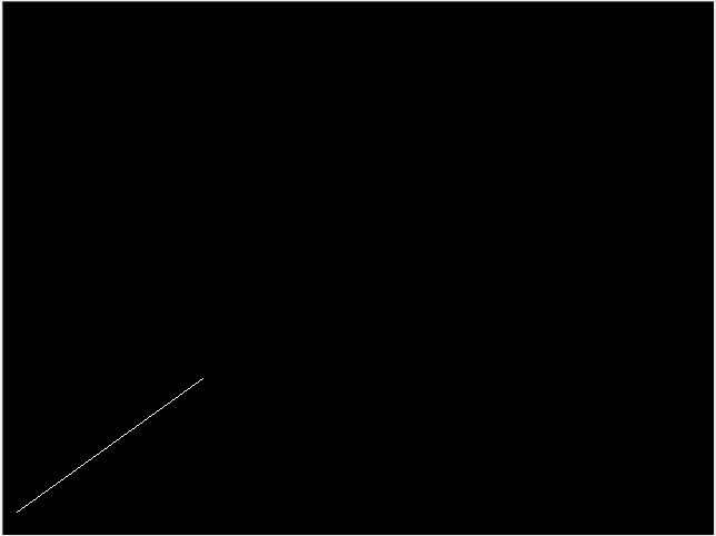
(1)直线两端点坐标:(13, 20)和(180,140); (2)直线颜色为白色。
3.输出
程序运行结果为一条直线,具体结果如下图所示:
二.相关知识
1.绘制点函数
image.set(x, y, color)函数是绘制点的函数,参数包括x、y和color。参数x为绘制点的x坐标,参数y为绘制点的y坐标,参数color为绘制点的颜色。
2.DDA算法
DDA算法相关知识点,请参考教材与课件或有关资料。
三.操作说明
(1)按要求补全line函数;
(2)点击窗口右下角"测评"按钮,等待测评结果,如果通过后可进行下一关任务。
#include "tgaimage.h"const TGAColor white = TGAColor(255, 255, 255, 255);
const TGAColor red = TGAColor(255, 0, 0, 255);void line(int x0, int y0, int x1, int y1, TGAImage &image, TGAColor color)
{// Please add the code here/********** Begin ********/int x;float y, k;k = (float)(y1 - y0) / (float)(x1 - x0);y = y0;for (x = x0;x <= x1;x++){image.set(x, int(y + 0.5f),color);y = y + k;}/********** End *********/
}int main(int argc, char** argv)
{TGAImage image(640,480, TGAImage::RGB);line(13, 20, 180, 140, image, white);image.flip_vertically(); // i want to have the origin at the left bottom corner of the imageimage.write_tga_file("../img_step1/test.tga");return 0;
}
第2关:直线光栅化-中点画线算法
一.任务描述
1.本关任务
(1)根据直线中点画线算法补全line函数,其中直线斜率0<k<1,并将main函数中的line函数参数补充完整; (2)当直线方程恰好经过P(x,y)和T(x,y+1)的中点M时,统一选取直线上方的T点为显示的像素点。
2.输入
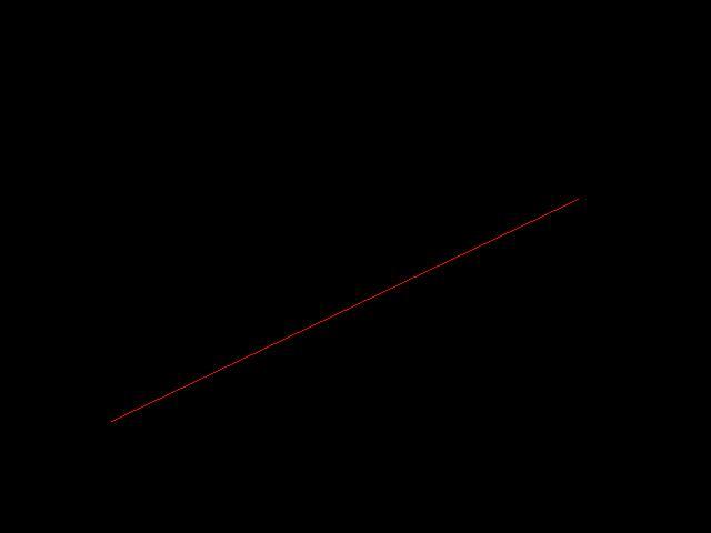
(1)直线两端点坐标:(100, 100)和(520,300); (2)直线颜色为红色。
3.输出
程序运行结果为一条直线,具体结果如下图所示:
二.相关知识
1.绘制点函数
image.set(x, y, color)函数是绘制点的函数,参数包括x、y和color。参数x为绘制点的x坐标,参数y为绘制点的y坐标,参数color为绘制点的颜色。
2.中点画线算法
中点画线算法相关知识点,请参考教材与课件或有关资料。
三.操作说明
(1)按要求补全line函数;
(2)点击窗口右下角"测评"按钮,等待测评结果,如果通过后可进行下一关任务。
#include "tgaimage.h"const TGAColor white = TGAColor(255, 255, 255, 255);
const TGAColor red = TGAColor(255, 0, 0, 255);void line(int x0, int y0, int x1, int y1, TGAImage &image, TGAColor color)
{// Please add the code here/********** Begin ********/int dx,dy,dt,db,d,x,y;dx = x1 - x0;dy = y1 - y0;d = dx - 2*dy;dt = 2*dx - 2*dy;db = -2*dy;x = x0;y = y0;image.set(x,y,color);while (x < x1){if (d <= 0){    x++;y++;d += dt;}else{x++;d += db;}image.set(x,y,color);}/********** End *********/
}int main(int argc, char** argv)
{TGAImage image(640,480, TGAImage::RGB);// Please add the code here/********** Begin ********/line( 100, 100 , 520 , 300 , image, red );/********** End *********/image.flip_vertically(); // i want to have the origin at the left bottom corner of the imageimage.write_tga_file("../img_step4/test.tga");return 0;
}
第3关:直线光栅化-Bresenham画线算法
一.任务描述
1.本关任务
(1)根据直线Bresenham算法补全line函数,其中直线斜率0<k<1,并将main函数中的line函数参数补充完整; (2)当直线方程恰好经过P(x,y)和T(x,y+1)的中点M时,统一选取直线上方的T点为显示的像素点。
2.输入
(1)直线两端点坐标:(20, 20)和(180,140); (2)直线颜色为白色。
3.输出
程序运行结果为一条直线,具体结果如下图所示:
二.相关知识
1.绘制点函数
image.set(x, y, color)函数是绘制点的函数,参数包括x、y和color。参数x为绘制点的x坐标,参数y为绘制点的y坐标,参数color为绘制点的颜色。
2.Bresenham算法
Bresenham算法相关知识点,请参考教材与课件或有关资料。
三.操作说明
(1)按要求补全line函数;
(2)点击窗口右下角"测评"按钮,等待测评结果,如果通过后可进行下一关任务。
#include "tgaimage.h"const TGAColor white = TGAColor(255, 255, 255, 255);
const TGAColor red = TGAColor(255, 0, 0, 255);void line(int x0, int y0, int x1, int y1, TGAImage &image, TGAColor color)
{// Please add the code here/********** Begin ********/int Dx=x1-x0,Dy=y1-y0,y=y0,D=-Dx;for(int x = x0;x <=x1;x++){image.set(x,y,color);D = D + 2*Dy;if(D >= 0){y++;D = D - 2*Dx;}}/********** End *********/
}int main(int argc, char** argv)
{TGAImage image(640,480, TGAImage::RGB);// Please add the code here/********** Begin ********/line( 20, 20 , 180 , 140 , image, white);/********** End *********/image.flip_vertically(); // i want to have the origin at the left bottom corner of the imageimage.write_tga_file("../img_step2/test.tga");return 0;
}
第4关:直线光栅化-任意斜率的Bresenham画线算法
一.任务描述
1.本关任务
(1)根据直线Bresenham算法补全line函数以绘制白色直线,其中直线斜率为任意情况。 (2)当直线方程恰好经过P(x,y)和T(x,y+1)的中点M时,统一选取直线上方的T点为显示的像素点。
2.输入
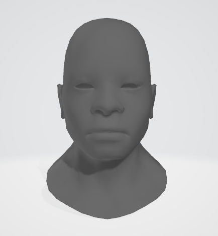
代码将自动输入一个OBJ三维人头模型,具体模型如下图:
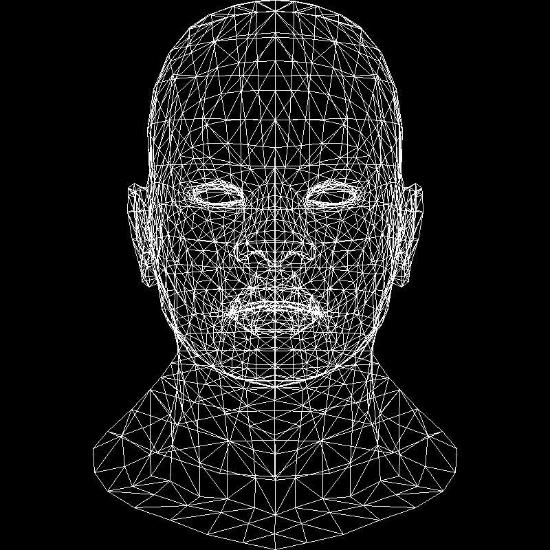
3.输出
若编写的任意斜率的Bresenham画线算法代码正确,则程序会将模型转换为线条图片,具体结果如下图所示:
二.相关知识
1.绘制点函数
image.set(x, y, color)函数是绘制点的函数,参数包括x、y和color。参数x为绘制点的x坐标,参数y为绘制点的y坐标,参数color为绘制点的颜色。
2.Bresenham算法
Bresenham算法相关知识点,请参考教材与课件或有关资料。
三.操作说明
(1)按要求补全line函数;
(2)点击窗口右下角"测评"按钮,等待测评结果,如果通过后可进行下一关任务。
CG2-v2.0-三角形填充
第1关:扫描线填充法
一. 任务描述
1. 本关任务
了解和掌握扫描线填充法,实现对三角形区域进行填充,具体要求如下: (1) 补全triangle函数; (2) 将main函数中的三角形顶点坐标和triangle函数参数补充完整。
2. 输入
(1) 三角形的三个顶点的坐标:
t0 = {125,50}, t1 = {300,200}, t2 ={200,350};
(2) 三角形区域为蓝色。3. 输出
程序运行结果为一个蓝色三角形区域,如下图所示:

#include "pngimage.h"
#include<stdio.h>
#include <iostream>struct Vec2i
{int x, y;
};void triangle(Vec2i t0, Vec2i t1, Vec2i t2, PNGImage& image, PNGColor color) {// Please add your code here/********** Begin ********/ if (t0.y>t1.y) std::swap(t0, t1); if (t0.y>t2.y) std::swap(t0, t2); if (t1.y>t2.y) std::swap(t1, t2);int total_height = t2.y-t0.y;for (int y=t0.y; y<=t1.y; y++) { int segment_height = t1.y-t0.y+1;    //be careful with divisions by zerofloat alpha = (float)(y-t0.y)/total_height,beta  = (float)(y-t0.y)/segment_height;   Vec2i A,B;A.y=B.y=y;A.x = t0.x + (t2.x-t0.x)*alpha; B.x = t0.x + (t1.x-t0.x)*beta; if (A.x>B.x) std::swap(A.x, B.x); for (int x=A.x; x<=B.x; x++) { image.set(x, y, color);  } }for (int y = t1.y; y <= t2.y; y++){int segment_height = t2.y-t1.y+1;    float alpha2=(float)(y-t0.y)/total_height,beta2 =(float)(y-t1.y)/segment_height;    Vec2i A2,B2;A2.y=B2.y=y;A2.x = t0.x + (t2.x-t0.x)*alpha2; B2.x = t1.x - (t1.x-t2.x)*beta2; if (A2.x>B2.x) std::swap(A2.x, B2.x); for (int x=A2.x; x<=B2.x; x++) { image.set(x, y, color);  } }
}/********** End **********/
int main(int argc, char** argv) {PNGColor white = PNGColor(255, 255, 255, 255);PNGColor black = PNGColor(0, 0, 0, 255);PNGColor red = PNGColor(255, 0, 0, 255);PNGColor blue = PNGColor(0, 255, 255, 255);int width = 400;int height = 400;PNGImage image(width, height, PNGImage::RGBA); //Error when RGB because lodepng_get_raw_size_lct(w, h, colortype, bitdepth) > in.size() in encodeimage.init(black);// Please add your code here/********** Begin ********/Vec2i t0 = {125 ,50 }, t1 = {300 , 200}, t2 = {200 ,350 };triangle( t0,t1 ,t2, image,PNGColor(0, 255, 255, 255)  );/********** End **********/image.flip_vertically(); // i want to have the origin at the left bottom corner of the imageimage.write_png_file("../img_step3/test.png");return 0;
}
第2关:重心坐标填充法
一. 任务描述
1. 本关任务
了解和掌握重心坐标法,以便能够对三角形区域进行填充,具体要求如下: (1) 补全Triangle和Barycenter函数; (2) 将main函数中的三角形顶点坐标和Triangle函数参数补充完整。
2. 输入
(1) 三角形的三个顶点的坐标:
t0 = {50,50}, t1 = {300,200}, t2 ={200,350};
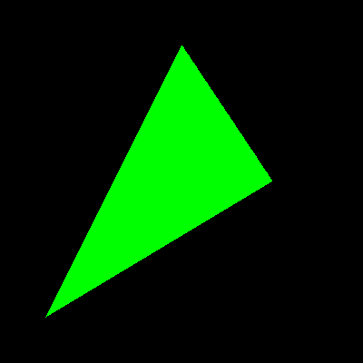
(2) 三角形颜色区域为绿色。3. 输出
程序运行结果为一个绿色三角形区域,如下图所示:
#include "pngimage.h"
#include<stdio.h>
#include <iostream>
#include <cmath>
#include <algorithm>
#include <stdlib.h>
struct Vec2i
{int x, y;
};
struct Vec3f
{float x, y, z;
};
//cross Product
Vec3f cross(const Vec3f& v1, const Vec3f& v2)
{Vec3f v3;v3.x = v1.y * v2.z - v1.z * v2.y;v3.y = v1.z * v2.x - v1.x * v2.z;v3.z = v1.x * v2.y - v1.y * v2.x;return v3;
}
//Determine the point p coordinates are in the triangle abc
Vec3f Barycentre(Vec2i p, Vec2i a, Vec2i b, Vec2i c)
{// Please add your code here/********** Begin ********/Vec3f s[2];s[0].x = c.x-a.x;s[0].y = b.x-a.x;s[0].z = a.x-p.x;s[1].x = c.y-a.y;s[1].y = b.y-a.y;s[1].z = a.y-p.y;Vec3f u = cross(s[0], s[1]);Vec3f v;if (abs(u.z) > 1e-2) {v.x = 1.0-(u.x+u.y)/u.z;v.y = u.y/u.z;v.z = u.x/u.z;} else {v.x = -1;v.y = 1;v.z = 1;}return v;/********** End ********/
}
// Please draw point to make a triangle in bounding box
void Triangle(Vec2i t0, Vec2i t1, Vec2i t2, PNGImage& image, PNGColor color)
{// Please add your code here/********** Begin ********/int xmax,ymax,x,y;xmax=400,ymax=400;Vec2i A;Vec3f v;for(x=0;x<=xmax;x++){for(y=0;y<=ymax;y++){A.x=x;A.y=y;v=Barycentre(A, t0, t1, t2);if(v.x>=0&&v.y>=0&&v.z>=0){image.set(x,y,color);}}}
}/********** End **********/
int main(int argc, char** argv) {PNGColor white = PNGColor(255, 255, 255, 255);PNGColor black = PNGColor(0, 0, 0, 255);PNGColor red = PNGColor(255, 0, 0, 255);PNGColor green = PNGColor(0, 255, 0, 255);    PNGColor blue = PNGColor(0, 255, 255, 255);int width = 400;int height = 400;PNGImage image(width, height, PNGImage::RGBA); //Error when RGB because lodepng_get_raw_size_lct(w, h, colortype, bitdepth) > in.size() in encodeimage.init(black);// Please add your code here/********** Begin ********/Vec2i t0={50,50},t1={300,200 },t2={200,350};Triangle(t0,t1,t2,image, PNGColor(0,255,0,255));/********** End **********/image.flip_vertically(); // i want to have the origin at the left bottom corner of the imageimage.write_png_file("../img_step2/test.png");return 0;
}
第3关:同侧判断填充法
一. 任务描述
1. 本关任务
了解和掌握同侧判断算法,以便能够对三角形区域进行填充,具体要求如下: (1) 并补全Triangle、SameSide和PointInTriangle函数; (2) 将main函数中的三角形顶点坐标和Triangle函数参数补充完整。
2. 输入
(1) 三角形的三个顶点的坐标:
t0 = {50,50}, t1 = {300,200}, t2 ={200,350};
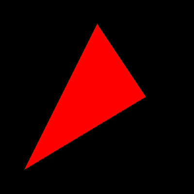
(2) 三角形区域为红色。3. 输出
程序运行结果为一个红色三角形区域,如下图所示:
#include "pngimage.h"
#include<stdio.h>
#include <iostream>
#include <algorithm>
using namespace std;
struct Vec2i
{int x, y;
};//Cross product
float CrossProduct(Vec2i a,Vec2i b)
{return a.x * b.y - b.x * a.y;
}
//DotProduct
float DotProduct(float cp1,float cp2)
{return cp1*cp2;
}
//Determine if P1 and P2 are on the same side
bool SameSide( Vec2i p,Vec2i a, Vec2i b, Vec2i c )
{// Please add your code here/********** Begin ********/Vec2i AB = {b.x - a.x, b.y - a.y};Vec2i AC = {c.x - a.x, c.y - a.y};Vec2i AP = {p.x - a.x, p.y - a.y};float v1 = CrossProduct(AB, AC);float v2 = CrossProduct(AB, AP);if (DotProduct(v1, v2) >= 0) return 1;else return 0;/********** End **********/
}
//Determine the point coordinates are in the triangle
float PointInTriangle(Vec2i p,Vec2i a, Vec2i b, Vec2i c)
{// Please add your code here/********** Begin ********/return SameSide(a, b, c, p) && SameSide(b, c, a, p) && SameSide(c, a, b, p); /********** End **********/
}// Please draw point in bounding box
void Triangle(Vec2i t0, Vec2i t1, Vec2i t2, PNGImage& image, PNGColor color)
{// Please add your code here/********** Begin ********/int xmax,ymax,x,y;Vec2i A;xmax=300,ymax=350;for(x=0;x<=xmax;x++){for(y=0;y<=ymax;y++){A.x=x;A.y=y;if(PointInTriangle(A,t0,t1 ,t2 ))image.set(x,y,color);}}/********** End **********/
}int main(int argc, char** argv) {PNGColor white = PNGColor(255, 255, 255, 255);PNGColor black = PNGColor(0, 0, 0, 255);PNGColor red = PNGColor(255, 0, 0, 255);PNGColor green = PNGColor(0, 255, 0, 255);    PNGColor blue = PNGColor(0, 255, 255, 255);int width = 400;int height = 400;PNGImage image(width, height, PNGImage::RGBA); //Error when RGB because lodepng_get_raw_size_lct(w, h, colortype, bitdepth) > in.size() in encodeimage.init(black);// Please add your code here/********** Begin ********/Vec2i t0 = { 50 , 50 }, t1 = {300  ,200  }, t2 = {200  ,350  };Triangle(t0 ,t1  , t2 , image, PNGColor(255, 0, 0, 255));/********** End **********/image.flip_vertically(); // i want to have the origin at the left bottom corner of the imageimage.write_png_file("../img_step1/test.png");return 0;
}
直线裁剪v1.0
第1关:Cohen-Sutherland编码裁剪算法
一. 任务描述
根据下面要求,在右侧修改代码,绘制出预期输出的图片。平台会对你编写的代码进行测试。
1.本关任务
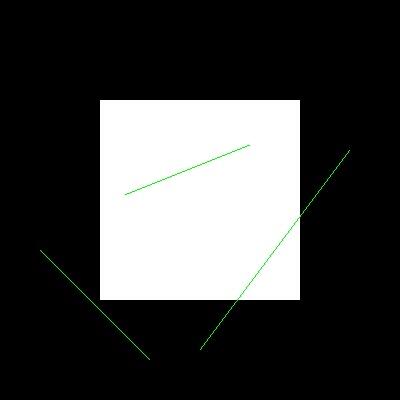
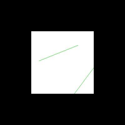
(1)理解直线裁剪的原理(Cohen-Surtherland算法、中点分割算法、梁友栋算法); (2)利用VC+OpenGL实现直线的编码裁剪算法,在屏幕上用一个封闭矩形裁剪任意一条直线; (3)调试、编译、修改程序;
2.运行前
3.输出
4.具体要求
(1)对CompCode(Point node, MyRect rect)函数进行补全; (2)对LineClipCohenSurtherland(MyRect rect, Point& node1, Point& node2)函数进行补全,最终实现裁剪后的图片。
// 评测代码所用头文件-开始
#include<opencv2/core/core.hpp>
#include<opencv2/highgui/highgui.hpp>
#include<opencv2/imgproc/imgproc.hpp>
// 评测代码所用头文件-结束// 提示:写完代码请保存之后再进行评测
#include <GL/freeglut.h>
#include <stdio.h>#define LEFT   1
#define RIGHT  2
#define BOTTOM 4
#define TOP    8struct MyRect
{int xmin, xmax, ymin, ymax;MyRect() : xmin(), xmax(), ymin(), ymax(){};MyRect(int a, int b, int c, int d) : xmin(a), xmax(b), ymin(c), ymax(d){};
};struct Point
{int x, y;Point() : x(), y() {};Point(int a, int b) :x(a), y(b) {};
};MyRect  rect;
Point vPoint[6];void LineGL(Point node1, Point node2)
{glBegin(GL_LINES);glColor3f(0.0f, 1.0f, 0.0f);   glVertex2f(node1.x, node1.y);glVertex2f(node2.x, node2.y);glEnd();
}int CompCode(Point node, MyRect rect)
{// 请在此添加你的代码/********** Begin ********/
int code = 0;if (node.x < rect.xmin)code |= LEFT;else if (node.x > rect.xmax)code |= RIGHT;if (node.y < rect.ymin)code |= BOTTOM;else if (node.y > rect.ymax)code |= TOP;return code;/********** End **********/
}void LineClipCohenSurtherland(MyRect rect, Point& node1, Point& node2)
{bool accept = false;// 请在此添加你的代码/********** Begin ********/int code1 = CompCode(node1, rect);int code2 = CompCode(node2, rect);while (true){if ((code1 | code2) == 0){accept = true;break;}else if (code1 & code2){break;}else{int code = (code1 != 0) ? code1 : code2;Point node;if (code & LEFT){node.x = rect.xmin;node.y = node1.y + (node2.y - node1.y) * (rect.xmin - node1.x) / (node2.x - node1.x);}else if (code & RIGHT){node.x = rect.xmax;node.y = node1.y + (node2.y - node1.y) * (rect.xmax - node1.x) / (node2.x - node1.x);}else if (code & BOTTOM){node.y = rect.ymin;node.x = node1.x + (node2.x - node1.x) * (rect.ymin - node1.y) / (node2.y - node1.y);}else if (code & TOP){node.y = rect.ymax;node.x = node1.x + (node2.x - node1.x) * (rect.ymax - node1.y) / (node2.y - node1.y);}if (code == code1){node1 = node;code1 = CompCode(node1, rect);}else{node2 = node;code2 = CompCode(node2, rect);}}}/********** End **********/if (accept)LineGL(node1, node2);
}void MyDisplay()
{glClear(GL_COLOR_BUFFER_BIT);glColor3f(1.0f, 1.0f, 1.0f);glRectf(rect.xmin, rect.ymin, rect.xmax, rect.ymax);for (int i = 0; i < 5; i+=2) LineClipCohenSurtherland(rect, vPoint[i], vPoint[i+1]);glFlush();
}void Init()
{glClearColor(0.0, 0.0, 0.0, 0.0);glShadeModel(GL_FLAT);rect = MyRect(100, 300, 100, 300);vPoint[0] = Point(200, 50); vPoint[1] = Point(350, 250);vPoint[2] = Point(125, 205); vPoint[3] = Point(250, 255);vPoint[4] = Point(40, 150); vPoint[5] = Point(150, 40);
}void MyReshape(int w, int h)
{glViewport(0, 0, (GLsizei)w, (GLsizei)h);glMatrixMode(GL_PROJECTION);glLoadIdentity();gluOrtho2D(0.0, (GLdouble)w, 0.0, (GLdouble)h);
}int main(int argc, char* argv[])
{glutInit(&argc, argv);glutInitDisplayMode(GLUT_RGB | GLUT_SINGLE);glutInitWindowPosition(100, 100);glutInitWindowSize(400, 400);glutCreateWindow("Hello World!");Init();glutDisplayFunc(MyDisplay);glutReshapeFunc(MyReshape);   glutMainLoopEvent(); /*************以下为评测代码,与本次实验内容无关,请勿修改**************/GLubyte* pPixelData = (GLubyte*)malloc(400 * 400 * 3);//分配内存GLint viewport[4] = {0};    glReadBuffer(GL_FRONT);glPixelStorei(GL_UNPACK_ALIGNMENT, 4);glGetIntegerv(GL_VIEWPORT, viewport);glReadPixels(viewport[0], viewport[1], viewport[2], viewport[3], GL_RGB, GL_UNSIGNED_BYTE, pPixelData);cv::Mat img;std::vector<cv::Mat> imgPlanes;img.create(400, 400, CV_8UC3);cv::split(img, imgPlanes);for(int i = 0; i < 400; i ++) {unsigned char* plane0Ptr = imgPlanes[0].ptr<unsigned char>(i);unsigned char* plane1Ptr = imgPlanes[1].ptr<unsigned char>(i);unsigned char* plane2Ptr = imgPlanes[2].ptr<unsigned char>(i);for(int j = 0; j < 400; j ++) {int k = 3 * (i * 400 + j);plane2Ptr[j] = pPixelData[k];plane1Ptr[j] = pPixelData[k+1];plane0Ptr[j] = pPixelData[k+2];}}cv::merge(imgPlanes, img);cv::flip(img, img ,0); cv::namedWindow("openglGrab");cv::imshow("openglGrab", img);cv::imwrite("../img_step1/test.jpg", img);return 0;
}
第2关:中点分割裁剪算法
一. 任务描述
根据下面要求,在右侧修改代码,绘制出预期输出的图片。平台会对你编写的代码进行测试。
1.本关任务
(1)理解直线裁剪的原理(Cohen-Surtherland算法、中点分割算法、梁友栋算法); (2)利用VC+OpenGL实现直线的编码裁剪算法,在屏幕上用一个封闭矩形裁剪任意一条直线; (3)调试、编译、修改程序;
2.运行前
3.输出
// 评测代码所用头文件-开始
#include<opencv2/core/core.hpp>
#include<opencv2/highgui/highgui.hpp>
#include<opencv2/imgproc/imgproc.hpp>
// 评测代码所用头文件-结束// 提示:写完代码请保存之后再进行评测
#include <GL/freeglut.h>
#include <stdio.h>#define LEFT   1
#define RIGHT  2
#define BOTTOM 4
#define TOP    8struct MyRect
{int xmin, xmax, ymin, ymax;MyRect() : xmin(), xmax(), ymin(), ymax(){};MyRect(int a, int b, int c, int d) : xmin(a), xmax(b), ymin(c), ymax(d){};
};struct Point
{int x, y;Point() : x(), y() {};Point(int a, int b) :x(a), y(b) {};
};MyRect  rect;
Point vPoint[6];void LineGL(Point node1, Point node2)
{glBegin(GL_LINES);glColor3f(0.0f, 1.0f, 0.0f);   glVertex2f(node1.x, node1.y);glVertex2f(node2.x, node2.y);glEnd();
}int CompCode(Point node, MyRect rect)
{int code = 0x00;if (node.y < rect.ymin)code = code | BOTTOM;if (node.y > rect.ymax)code = code | TOP;if (node.x > rect.xmax)code = code | RIGHT;if (node.x < rect.xmin)code = code | LEFT;return code;
}void LineClipMidPoint(MyRect rect, Point& node1, Point& node2)
{bool accept = true;Point start, end, mid;//分别代表起点,终点和中点int code1, code2, codemid;code1 = CompCode(node1, rect);code2 = CompCode(node2, rect);if(code1 == 0 && code2 == 0)accept = true;else if(code1 & code2)accept = false;else {if(code2!=0){start = node1; end = node2;mid = Point((float)(start.x + end.x)/(float)2 + 0.5, (float)(start.y + end.y)/(float)2 + 0.5);while(abs(start.x - mid.x)>1 || abs(start.y - mid.y)>1){codemid = CompCode(mid, rect);if(codemid==0){start = mid;} else{end = mid;}mid = Point((float)(start.x + end.x)/(float)2 + 0.5, (float)(start.y + end.y)/(float)2 + 0.5);}node2 = mid;}if(code1!=0){start = node1; end = node2;mid = Point((float)(start.x + end.x)/(float)2 + 0.5, (float)(start.y + end.y)/(float)2 + 0.5);while(abs(start.x - mid.x)>1 || abs(start.y - mid.y)>1){codemid = CompCode(mid, rect);if(codemid==0){end = mid;}else{start = mid;}mid = Point((float)(start.x + end.x)/(float)2 + 0.5, (float)(start.y + end.y)/(float)2 + 0.5);}node1 = mid;}}if (accept)LineGL(node1, node2);
}void MyDisplay()
{glClear(GL_COLOR_BUFFER_BIT);glColor3f(1.0f, 1.0f, 1.0f);glRectf(rect.xmin, rect.ymin, rect.xmax, rect.ymax);for (int i = 0; i < 5; i+=2) LineClipMidPoint(rect, vPoint[i], vPoint[i+1]);glFlush();
}void Init()
{glClearColor(0.0, 0.0, 0.0, 0.0);glShadeModel(GL_FLAT);rect = MyRect(100, 300, 100, 300);vPoint[0] = Point(200, 50); vPoint[1] = Point(350, 250);vPoint[2] = Point(125, 205); vPoint[3] = Point(250, 255);vPoint[4] = Point(40, 150); vPoint[5] = Point(150, 40);
}void MyReshape(int w, int h)
{glViewport(0, 0, (GLsizei)w, (GLsizei)h);glMatrixMode(GL_PROJECTION);glLoadIdentity();gluOrtho2D(0.0, (GLdouble)w, 0.0, (GLdouble)h);
}int main(int argc, char* argv[])
{glutInit(&argc, argv);glutInitDisplayMode(GLUT_RGB | GLUT_SINGLE);glutInitWindowPosition(100, 100);glutInitWindowSize(400, 400);glutCreateWindow("Hello World!");Init();glutDisplayFunc(MyDisplay);glutReshapeFunc(MyReshape);   glutMainLoopEvent(); /*************以下为评测代码,与本次实验内容无关,请勿修改**************/GLubyte* pPixelData = (GLubyte*)malloc(400 * 400 * 3);//分配内存GLint viewport[4] = {0};    glReadBuffer(GL_FRONT);glPixelStorei(GL_UNPACK_ALIGNMENT, 4);glGetIntegerv(GL_VIEWPORT, viewport);glReadPixels(viewport[0], viewport[1], viewport[2], viewport[3], GL_RGB, GL_UNSIGNED_BYTE, pPixelData);cv::Mat img;std::vector<cv::Mat> imgPlanes;img.create(400, 400, CV_8UC3);cv::split(img, imgPlanes);for(int i = 0; i < 400; i ++) {unsigned char* plane0Ptr = imgPlanes[0].ptr<unsigned char>(i);unsigned char* plane1Ptr = imgPlanes[1].ptr<unsigned char>(i);unsigned char* plane2Ptr = imgPlanes[2].ptr<unsigned char>(i);for(int j = 0; j < 400; j ++) {int k = 3 * (i * 400 + j);plane2Ptr[j] = pPixelData[k];plane1Ptr[j] = pPixelData[k+1];plane0Ptr[j] = pPixelData[k+2];}}cv::merge(imgPlanes, img);cv::flip(img, img ,0); cv::namedWindow("openglGrab");cv::imshow("openglGrab", img);cv::imwrite("../img_step3/test.jpg", img);return 0;
}
4.具体要求
对LineClipMidPoint(MyRect rect, Point& node1, Point& node2)函数进行补全,最终实现裁剪后的图片。
第3关:Liang-Barsky参数化裁剪算法
一. 任务描述
根据下面要求,在右侧修改代码,绘制出预期输出的图片。平台会对你编写的代码进行测试。
1.本关任务
(1)理解直线裁剪的原理(Cohen-Surtherland算法、中点分割算法、梁友栋算法); (2)利用VC+OpenGL实现直线的编码裁剪算法,在屏幕上用一个封闭矩形裁剪任意一条直线; (3)调试、编译、修改程序;
2.运行前
3.输出
4.具体要求
(1)对ClipTest(float p, float q, float* u1, float* u2)函数进行补全; (2)对LineClipLiangBarsky(MyRect rect, Point& node1, Point& node2)函数进行补全,最终实现裁剪后的图片。
// 评测代码所用头文件-开始
#include<opencv2/core/core.hpp>
#include<opencv2/highgui/highgui.hpp>
#include<opencv2/imgproc/imgproc.hpp>
// 评测代码所用头文件-结束// 提示:写完代码请保存之后再进行评测
#include <GL/freeglut.h>
#include <stdio.h>struct MyRect
{int xmin, xmax, ymin, ymax;MyRect() : xmin(), xmax(), ymin(), ymax(){};MyRect(int a, int b, int c, int d) : xmin(a), xmax(b), ymin(c), ymax(d){};
};struct Point
{int x, y;Point() : x(), y() {};Point(int a, int b) :x(a), y(b) {};
};MyRect  rect;
Point vPoint[6];void LineGL(Point node1, Point node2)
{glBegin(GL_LINES);glColor3f(0.0f, 1.0f, 0.0f);   glVertex2f(node1.x, node1.y);glVertex2f(node2.x, node2.y);glEnd();
}int ClipTest(float p, float q, float* u1, float* u2)
{if (p < 0.0){float r = q / p;if (r > *u2){return 0;}else if (r > *u1){*u1 = r;}}else if (p > 0.0){float r = q / p;if (r < *u1){return 0;}else if (r < *u2){*u2 = r;}}else if (q < 0.0){return 0;}return 1;
}bool LineClipLiangBarsky(MyRect rect, Point& node1, Point& node2)
{float u1 = 0.0, u2 = 1.0;int dx = node2.x - node1.x;int dy = node2.y - node1.y;if (ClipTest(-dx, node1.x - rect.xmin, &u1, &u2)){if (ClipTest(dx, rect.xmax - node1.x, &u1, &u2)){if (ClipTest(-dy, node1.y - rect.ymin, &u1, &u2)){if (ClipTest(dy, rect.ymax - node1.y, &u1, &u2)){if (u2 < 1.0){node2.x = node1.x + u2*dx;node2.y = node1.y + u2*dy;}if (u1 > 0.0){node1.x = node1.x + u1*dx;node1.y = node1.y + u1*dy;}return true;}}}}return false;
}void MyDisplay()
{glClear(GL_COLOR_BUFFER_BIT);glColor3f(1.0f, 1.0f, 1.0f);glRectf(rect.xmin, rect.ymin, rect.xmax, rect.ymax);for(int i = 0; i < 5; i+=2){bool bAccept = LineClipLiangBarsky(rect, vPoint[i], vPoint[i+1]);if(bAccept)LineGL(vPoint[i], vPoint[i+1]);}glFlush();
}void Init()
{glClearColor(0.0, 0.0, 0.0, 0.0);glShadeModel(GL_FLAT);rect = MyRect(100, 300, 100, 300);vPoint[0] = Point(200, 50); vPoint[1] = Point(350, 250);vPoint[2] = Point(125, 205); vPoint[3] = Point(250, 255);vPoint[4] = Point(40, 150); vPoint[5] = Point(150, 40);
}void MyReshape(int w, int h)
{glViewport(0, 0, (GLsizei)w, (GLsizei)h);glMatrixMode(GL_PROJECTION);glLoadIdentity();gluOrtho2D(0.0, (GLdouble)w, 0.0, (GLdouble)h);
}int main(int argc, char* argv[])
{glutInit(&argc, argv);glutInitDisplayMode(GLUT_RGB | GLUT_SINGLE);glutInitWindowPosition(100, 100);glutInitWindowSize(400, 400);glutCreateWindow("Hello World!");Init();glutDisplayFunc(MyDisplay);glutReshapeFunc(MyReshape);   glutMainLoopEvent(); /*************以下为评测代码,与本次实验内容无关,请勿修改**************/GLubyte* pPixelData = (GLubyte*)malloc(400 * 400 * 3);//分配内存GLint viewport[4] = {0};    glReadBuffer(GL_FRONT);glPixelStorei(GL_UNPACK_ALIGNMENT, 4);glGetIntegerv(GL_VIEWPORT, viewport);glReadPixels(viewport[0], viewport[1], viewport[2], viewport[3], GL_RGB, GL_UNSIGNED_BYTE, pPixelData);cv::Mat img;std::vector<cv::Mat> imgPlanes;img.create(400, 400, CV_8UC3);cv::split(img, imgPlanes);for(int i = 0; i < 400; i ++) {unsigned char* plane0Ptr = imgPlanes[0].ptr<unsigned char>(i);unsigned char* plane1Ptr = imgPlanes[1].ptr<unsigned char>(i);unsigned char* plane2Ptr = imgPlanes[2].ptr<unsigned char>(i);for(int j = 0; j < 400; j ++) {int k = 3 * (i * 400 + j);plane2Ptr[j] = pPixelData[k];plane1Ptr[j] = pPixelData[k+1];plane0Ptr[j] = pPixelData[k+2];}}cv::merge(imgPlanes, img);cv::flip(img, img ,0); cv::namedWindow("openglGrab");cv::imshow("openglGrab", img);cv::imwrite("../img_step2/test.jpg", img);return 0;
}
CG2-v1.0-二维几何变换
第1关:正方形的平移与缩放
一.任务描述
根据提示,在右侧修改代码,并自己绘制出图形。平台会对你编写的代码进行测试。
1.本关任务
理解并掌握OpenGL二维平移、旋转、缩放变换的方法; 阅读实验原理,掌握OpenGL程序平移、旋转、缩放变换的方法。
2.预期输出
3.具体要求
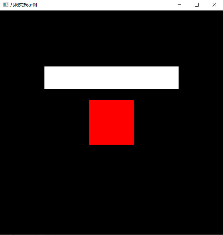
(1).背景色为黑色,用 glClearColor() 来完成; (2).以中心为绘制原点,设计一个边长为2的正方形将正方形设置为红色glColor3f(1.0, 0.0, 0.0); (3).将原正方形保留下来并以正方形为基础,然后进行二维几何变换。将正方形向上平移2.0,同时将正方形沿X方向放大3倍,沿Y方向缩小成原来的0.5倍。新生成的矩形颜色为白色glColor3f (1.0, 1.0, 1.0)。
4.本关提示
(1).用glRectf()函数来绘制正方形; (2).每进行一个矩阵操作时,需要先保存这个矩阵,调用glPushMatrix()函数,把当前矩阵压入堆栈。当需要恢复最近一次的保存时,调用glPopMatrix()函数,它相当于从堆栈栈顶弹出一个矩阵为当前矩阵(后边的三关都会用到)。
// 提示:写完代码请保存之后再进行评测
#include <GL/freeglut.h>
#include<stdio.h>// 评测代码所用头文件-开始
#include<opencv2/core/core.hpp>
#include<opencv2/highgui/highgui.hpp>
#include<opencv2/imgproc/imgproc.hpp>
// 评测代码所用头文件-结束void init(void)
{  glClearColor(0.0, 0.0, 0.0, 0.0);       //设置背景颜色glMatrixMode(GL_PROJECTION);gluOrtho2D(-5.0, 5.0, -5.0, 5.0);       //设置显示的范围是X:-5.0~5.0, Y:-5.0~5.0glMatrixMode(GL_MODELVIEW);
}void myDraw(void)                           //二维几何变换
{// 请在此添加你的代码/********** Begin ********/glPushMatrix();glColor3f(1.0, 0.0, 0.0);glRectf(-1.0f, - 1.0f,1.0f,1.0f);glPopMatrix();glPushMatrix();glTranslatef(0.0f,2.0f,0.0f);glPushMatrix();glScalef(3.0,0.5,1.0);glColor3f (1.0, 1.0, 1.0);glRectf(-1.0f, - 1.0f,1.0f,1.0f);glFlush();/********** End **********/                          glFlush();
}int main(int argc, char *argv[])
{glutInit(&argc, argv);glutInitWindowPosition(100, 100);glutInitWindowSize(400, 400);glutCreateWindow("几何变换示例");init();glutDisplayFunc(&myDraw);glutMainLoopEvent();     /*************以下为评测代码,与本次实验内容无关,请勿修改**************/GLubyte* pPixelData = (GLubyte*)malloc(400 * 400 * 3);//分配内存GLint viewport[4] = {0};glReadBuffer(GL_FRONT);glPixelStorei(GL_UNPACK_ALIGNMENT, 4);glGetIntegerv(GL_VIEWPORT, viewport);glReadPixels(viewport[0], viewport[1], viewport[2], viewport[3], GL_RGB, GL_UNSIGNED_BYTE, pPixelData);cv::Mat img;std::vector<cv::Mat> imgPlanes;img.create(400, 400, CV_8UC3);cv::split(img, imgPlanes);for(int i = 0; i < 400; i ++) {unsigned char* plane0Ptr = imgPlanes[0].ptr<unsigned char>(i);unsigned char* plane1Ptr = imgPlanes[1].ptr<unsigned char>(i);unsigned char* plane2Ptr = imgPlanes[2].ptr<unsigned char>(i);for(int j = 0; j < 400; j ++) {int k = 3 * (i * 400 + j);plane2Ptr[j] = pPixelData[k];plane1Ptr[j] = pPixelData[k+1];plane0Ptr[j] = pPixelData[k+2];}}cv::merge(imgPlanes, img);cv::flip(img, img ,0); cv::namedWindow("openglGrab");cv::imshow("openglGrab", img);//cv::waitKey();cv::imwrite("../img_step1/test.jpg", img);return 0;
}
第2关:正方形的平移和旋转
一.任务描述
根据提示,在右侧修改代码,并自己绘制出图形。平台会对你编写的代码进行测试。
1.本关任务
理解并掌握OpenGL二维平移、旋转、缩放变换的方法; 阅读实验原理,掌握OpenGL程序平移、旋转、缩放变换的方法。
2.预期输出
3.具体要求
(1).背景色为黑色,用 glclearcolor 来完成; (2).以中心为绘制原点,设计一个边长为2的正方形将正方形设置为红色glColor3f(1.0, 0.0, 0.0); (3).将原正方形保留下来并以正方形为基础,然后进行二维几何变换。将正方形向左平移3.0,同时将正方形沿X轴逆时针旋转45度,生成新的图形颜色为glColor3f (0.0, 1.0, 0.0); (4).再进行二维几何变换,将原正方形向右平移3.0,同时将正方形沿X轴逆时针旋转45度,生成新的图形颜色为glColor3f (0.0, 0.7, 0.0);
4.本关提示
(1).用glRectf()函数来绘制正方形; (2).每进行一个矩阵操作时,需要先保存这个矩阵,调用glPushMatrix()函数,把当前矩阵压入堆栈。当需要恢复最近一次的保存时,调用glPopMatrix()函数,它相当于从堆栈栈顶弹出一个矩阵为当前矩阵。
// 提示:写完代码请保存之后再进行评测
#include <GL/freeglut.h>
#include<stdio.h>// 评测代码所用头文件-开始
#include<opencv2/core/core.hpp>
#include<opencv2/highgui/highgui.hpp>
#include<opencv2/imgproc/imgproc.hpp>
// 评测代码所用头文件-结束void init(void)
{  glClearColor(0.0, 0.0, 0.0, 0.0);       //设置背景颜色glMatrixMode(GL_PROJECTION);gluOrtho2D(-5.0, 5.0, -5.0, 5.0);       //设置显示的范围是X:-5.0~5.0, Y:-5.0~5.0glMatrixMode(GL_MODELVIEW);
}void myDraw(void)                           //二维几何变换
{// 请在此添加你的代码glPushMatrix();glColor3f(1.0, 0.0, 0.0);glRectf(-1.0f, - 1.0f,1.0f,1.0f);glPopMatrix();//glPushMatrix();glTranslatef(-3.0f,0.0f,0.0f);glPushMatrix();glRotatef(45.0,0.0,0.0,1.0);glColor3f (0.0, 1.0, 0.0);glRectf(-1.0f, - 1.0f,1.0f,1.0f);glPopMatrix();glTranslatef(6.0f,0.0f,0.0f);glPushMatrix();glRotatef(45.0,0.0,0.0,1.0);glColor3f (0.0, 0.7, 0.0);glRectf(-1.0f, - 1.0f,1.0f,1.0f);glPopMatrix();glFlush();/********** End **********/                          glFlush();
}int main(int argc, char *argv[])
{glutInit(&argc, argv);glutInitWindowPosition(100, 100);glutInitWindowSize(400, 400);glutCreateWindow("几何变换示例");init();glutDisplayFunc(&myDraw);glutMainLoopEvent();     /*************以下为评测代码,与本次实验内容无关,请勿修改**************/GLubyte* pPixelData = (GLubyte*)malloc(400 * 400 * 3);//分配内存GLint viewport[4] = {0};glReadBuffer(GL_FRONT);glPixelStorei(GL_UNPACK_ALIGNMENT, 4);glGetIntegerv(GL_VIEWPORT, viewport);glReadPixels(viewport[0], viewport[1], viewport[2], viewport[3], GL_RGB, GL_UNSIGNED_BYTE, pPixelData);cv::Mat img;std::vector<cv::Mat> imgPlanes;img.create(400, 400, CV_8UC3);cv::split(img, imgPlanes);for(int i = 0; i < 400; i ++) {unsigned char* plane0Ptr = imgPlanes[0].ptr<unsigned char>(i);unsigned char* plane1Ptr = imgPlanes[1].ptr<unsigned char>(i);unsigned char* plane2Ptr = imgPlanes[2].ptr<unsigned char>(i);for(int j = 0; j < 400; j ++) {int k = 3 * (i * 400 + j);plane2Ptr[j] = pPixelData[k];plane1Ptr[j] = pPixelData[k+1];plane0Ptr[j] = pPixelData[k+2];}}cv::merge(imgPlanes, img);cv::flip(img, img ,0); cv::namedWindow("openglGrab");cv::imshow("openglGrab", img);//cv::waitKey();cv::imwrite("../img_step2/test.jpg", img);return 0;
}
第3关:正方形的变换组合
一.任务描述
根据提示,在右侧修改代码,并自己绘制出图形。平台会对你编写的代码进行测试。
1.本关任务
理解并掌握OpenGL二维平移、旋转、缩放变换的方法; 阅读实验原理,掌握OpenGL程序平移、旋转、缩放变换的方法。
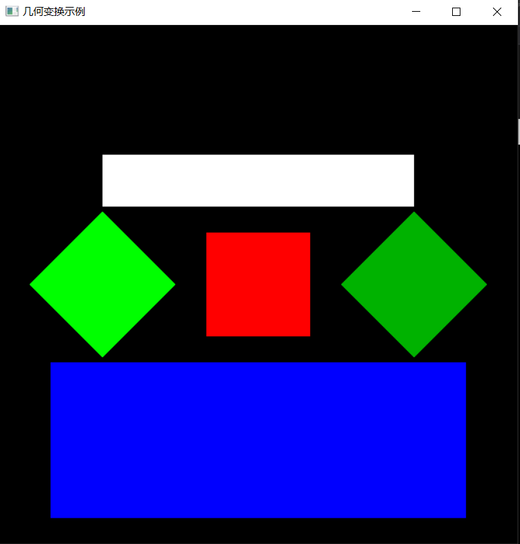
2.预期输出
3.具体要求
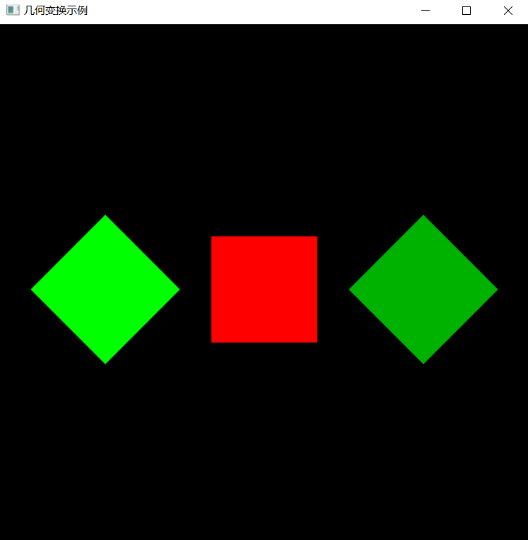
(1).背景色为黑色,用 glclearcolor 来完成; (2).以中心为绘制原点,设计一个边长为2的正方形将正方形设置为红色glColor3f(1.0, 0.0, 0.0); (3).完成前两关的内容; (4).将原正方形进行二维几何变换。将正方形向下平移3.0,同时将正方形沿X方向放大4倍,沿Y方向扩大成原来的1.5倍。新生成的矩形颜色为蓝色glColor3f (0.0, 0.0, 1.0)。
4.本关提示
(1).用glRectf()函数来绘制正方形; (2).每进行一个矩阵操作时,需要先保存这个矩阵,调用glPushMatrix()函数,把当前矩阵压入堆栈。当需要恢复最近一次的保存时,调用glPopMatrix()函数,它相当于从堆栈栈顶弹出一个矩阵为当前矩阵。
// 提示:写完代码请保存之后再进行评测
#include <GL/freeglut.h>
#include<stdio.h>// 评测代码所用头文件-开始
#include<opencv2/core/core.hpp>
#include<opencv2/highgui/highgui.hpp>
#include<opencv2/imgproc/imgproc.hpp>
// 评测代码所用头文件-结束void init(void)
{  glClearColor(0.0, 0.0, 0.0, 0.0);       //设置背景颜色glMatrixMode(GL_PROJECTION);gluOrtho2D(-5.0, 5.0, -5.0, 5.0);       //设置显示的范围是X:-5.0~5.0, Y:-5.0~5.0glMatrixMode(GL_MODELVIEW);
}void myDraw(void)                           //二维几何变换
{// 请在此添加你的代码/********** Begin ********/glClear (GL_COLOR_BUFFER_BIT); //清空glLoadIdentity(); //将当前矩阵设为单位矩阵glPushMatrix();glTranslatef(0.0f,2.0f,0.0f);glScalef(3.0,0.5,1.0);glColor3f (1.0, 1.0, 1.0);glRectf(-1.0f, -1.0f, 1.0f, 1.0f); //上面白色矩形glPopMatrix();glPushMatrix();glTranslatef(-3.0,0.0,0.0);glPushMatrix();glRotatef(45.0,0.0,0.0,1.0);glColor3f (0.0, 1.0, 0.0);glRectf(-1.0f, -1.0f, 1.0f, 1.0f); //中间左菱形glPopMatrix();glTranslatef(3.0,0.0,0.0);glPushMatrix();glColor3f (1.0, 0.0, 0.0);glRectf(-1.0f, -1.0f, 1.0f, 1.0f); //中间中菱形glPopMatrix();glTranslatef(3.0,0.0,0.0);glPushMatrix();glRotatef(45.0,0.0,0.0,1.0);glColor3f (0.0, 0.7, 0.0);glRectf(-1.0f, -1.0f, 1.0f, 1.0f); //中间右菱形glPopMatrix();glPopMatrix();glTranslatef(0.0,-3.0,0.0);glScalef(4.0,1.5,1.0);glColor3f (0.0, 0.0, 1.0);glRectf(-1.0f, -1.0f, 1.0f, 1.0f); //下面蓝色矩形glFlush ( );/********** End **********/                          glFlush();
}int main(int argc, char *argv[])
{glutInit(&argc, argv);glutInitWindowPosition(100, 100);glutInitWindowSize(400, 400);glutCreateWindow("几何变换示例");init();glutDisplayFunc(&myDraw);glutMainLoopEvent();     /*************以下为评测代码,与本次实验内容无关,请勿修改**************/GLubyte* pPixelData = (GLubyte*)malloc(400 * 400 * 3);//分配内存GLint viewport[4] = {0};glReadBuffer(GL_FRONT);glPixelStorei(GL_UNPACK_ALIGNMENT, 4);glGetIntegerv(GL_VIEWPORT, viewport);glReadPixels(viewport[0], viewport[1], viewport[2], viewport[3], GL_RGB, GL_UNSIGNED_BYTE, pPixelData);cv::Mat img;std::vector<cv::Mat> imgPlanes;img.create(400, 400, CV_8UC3);cv::split(img, imgPlanes);for(int i = 0; i < 400; i ++) {unsigned char* plane0Ptr = imgPlanes[0].ptr<unsigned char>(i);unsigned char* plane1Ptr = imgPlanes[1].ptr<unsigned char>(i);unsigned char* plane2Ptr = imgPlanes[2].ptr<unsigned char>(i);for(int j = 0; j < 400; j ++) {int k = 3 * (i * 400 + j);plane2Ptr[j] = pPixelData[k];plane1Ptr[j] = pPixelData[k+1];plane0Ptr[j] = pPixelData[k+2];}}cv::merge(imgPlanes, img);cv::flip(img, img ,0); cv::namedWindow("openglGrab");cv::imshow("openglGrab", img);//cv::waitKey();cv::imwrite("../img_step3/test.jpg", img);return 0;
}
第4关:三菱形状
一.任务描述
根据提示,在右侧修改代码,并自己绘制出图形。平台会对你编写的代码进行测试。
1.本关任务
理解并掌握OpenGL二维平移、旋转、缩放变换的方法; 阅读实验原理,掌握OpenGL程序平移、旋转、缩放变换的方法; 利用虚拟机进行编程,以OpenGL为开发平台设计程序,设计二维几何变换图形。
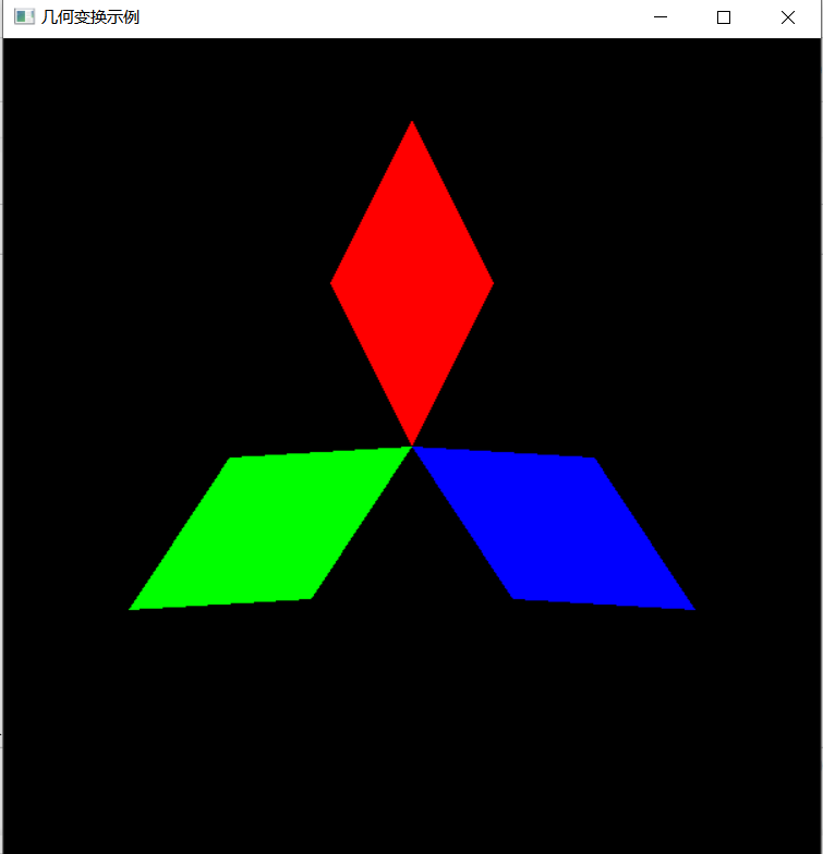
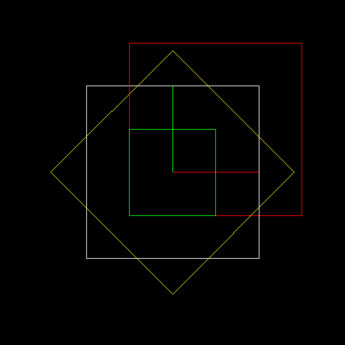
2.预期输出
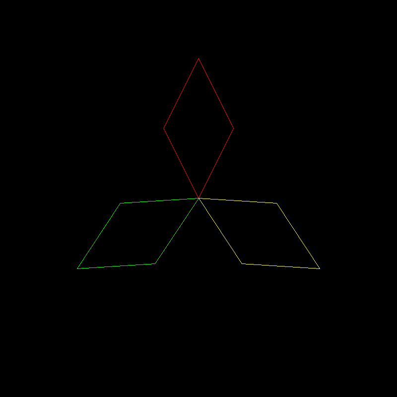
设计如图所示二维图形
3.具体要求
(1).背景色为黑色,用 glclearcolor 来完成; (2).三个菱形图形通过二维平移和旋转完成。颜色分别为红色(1.0, 0.0, 0.0)、蓝色(0.0, 0.0, 1.0)和绿色(0.0, 1.0, 0.0); (3).三个菱形的长对角线长度为4.0,短对角线长度为2.0,三个菱形的交点为原点(0.0,0.0); (4).红色菱形的长对角线与Y轴重合,每个菱形的长对角线夹角为120度。
4.本关提示
(1).可将绘制原始的图形设置成一个单独的函数便于调用,这样可以省去反复绘制原始图形的步骤; (2).画一个凸多边形可以调用glBegin(GL_POLYGON),后边用glVertex2f( , )指定顶点坐标,需要注意凸多边形的顶点指定需要按逆时针方向; (3).保留原始图形可以看做调用平移函数并且平移的距离为(0.0,0.0,0.0); (4).每进行一个矩阵操作时,需要先保存这个矩阵,调用glPushMatrix()函数,把当前矩阵压入堆栈。当需要恢复最近一次的保存时,调用glPopMatrix()函数,它相当于从堆栈栈顶弹出一个矩阵为当前矩阵。
// 提示:写完代码请保存之后再进行评测
#include <GL/freeglut.h>
#include<stdio.h>// 评测代码所用头文件-开始
#include<opencv2/core/core.hpp>
#include<opencv2/highgui/highgui.hpp>
#include<opencv2/imgproc/imgproc.hpp>
// 评测代码所用头文件-结束void init(void)
{  glClearColor(0.0, 0.0, 0.0, 0.0);       //设置背景颜色glMatrixMode(GL_PROJECTION);gluOrtho2D(-5.0, 5.0, -5.0, 5.0);       //设置显示的范围是X:-5.0~5.0, Y:-5.0~5.0glMatrixMode(GL_MODELVIEW);
}
void drawDiamond(void)                        //绘制一个菱形
{// 请在此添加你的代码/********** Begin ********/glBegin (GL_POLYGON); //顶点指定需要按逆时针方向glVertex2f (0.0f,-1.0f);//下点glVertex2f (2.0f,0.0f);//右点glVertex2f (0.0f, 1.0f);//上点glVertex2f (-2.0f,0.0f);//左点glEnd ( );/********** End **********/
}void myDraw(void)                           //二维几何变换
{// 请在此添加你的代码/********** Begin ********/glClear(GL_COLOR_BUFFER_BIT); //清空glLoadIdentity(); //将当前矩阵设为单位矩阵glPushMatrix();glRotatef(30.0, 0.0, 0.0, 1.0);glTranslatef(-2.0, 0.0, 0.0);glColor3f(0.0, 1.0, 0.0);drawDiamond();glPopMatrix();glPushMatrix();glRotatef(150.0, 0.0, 0.0, 1.0);glTranslatef(-2.0, 0.0, 0.0);glColor3f(0.0, 0.0, 1.0);drawDiamond();glPopMatrix();glPushMatrix();glRotatef(270.0, 0.0, 0.0, 1.0);glTranslatef(-2.0, 0.0, 0.0);glColor3f(1.0, 0.0, 0.0);drawDiamond();/********** End **********/                          glFlush();
}int main(int argc, char *argv[])
{glutInit(&argc, argv);glutInitWindowPosition(100, 100);glutInitWindowSize(400, 400);glutCreateWindow("几何变换示例");init();glutDisplayFunc(&myDraw);glutMainLoopEvent();     /*************以下为评测代码,与本次实验内容无关,请勿修改**************/GLubyte* pPixelData = (GLubyte*)malloc(400 * 400 * 3);//分配内存GLint viewport[4] = {0};glReadBuffer(GL_FRONT);glPixelStorei(GL_UNPACK_ALIGNMENT, 4);glGetIntegerv(GL_VIEWPORT, viewport);glReadPixels(viewport[0], viewport[1], viewport[2], viewport[3], GL_RGB, GL_UNSIGNED_BYTE, pPixelData);cv::Mat img;std::vector<cv::Mat> imgPlanes;img.create(400, 400, CV_8UC3);cv::split(img, imgPlanes);for(int i = 0; i < 400; i ++) {unsigned char* plane0Ptr = imgPlanes[0].ptr<unsigned char>(i);unsigned char* plane1Ptr = imgPlanes[1].ptr<unsigned char>(i);unsigned char* plane2Ptr = imgPlanes[2].ptr<unsigned char>(i);for(int j = 0; j < 400; j ++) {int k = 3 * (i * 400 + j);plane2Ptr[j] = pPixelData[k];plane1Ptr[j] = pPixelData[k+1];plane0Ptr[j] = pPixelData[k+2];}}cv::merge(imgPlanes, img);cv::flip(img, img ,0); cv::namedWindow("openglGrab");cv::imshow("openglGrab", img);//cv::waitKey();cv::imwrite("../img_step4/test.jpg", img);return 0;
}
CG3-v2.0-图形几何变换
第1关:平移、缩放、旋转正方体
一. 任务描述
1. 本关任务
(1) 理解几何变换基本原理, 掌握平移、旋转、缩放变换的方法; (2) 根据平移算法原理补全translation、scale、rotation_x、rotation_y和rotation_z函数; (3) 根据几何变换基本原理,将main函数中的translation、scale、rotation_z参数补充完整。
2. 输入
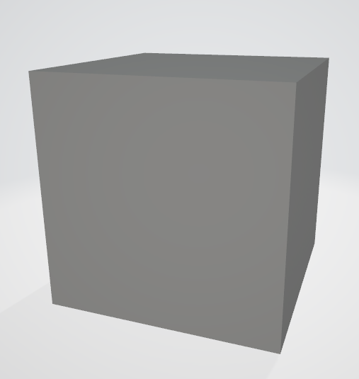
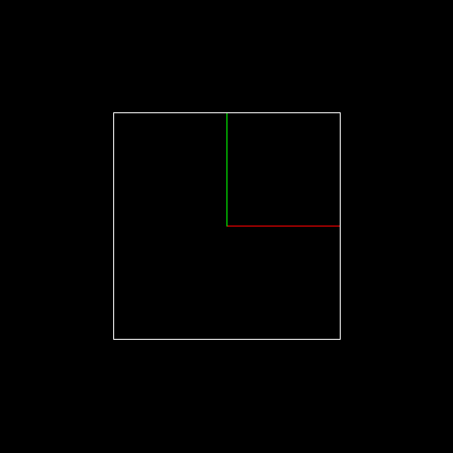
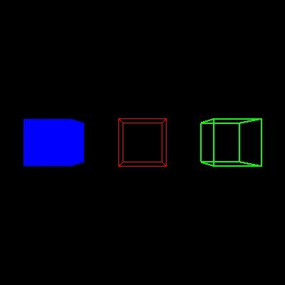
(1) 代码将自动输入一个边长为2的obj正方体模型,具体模型如下图:
(2) 代码自动将模型投影到二维平面上生成一个边长为1的白色正方形,并且代码会生成红色x轴,绿色y轴,具体图片如下所示:
(3) 将立方体的顶点坐标分别向x,y,z轴正方向平移0.5个单位距离,然后绘制一个红色正方形; (4) 将立方体的顶点坐标分别沿x,y,z轴方向缩放0.5倍,然后绘制一个绿色正方形; (5) 将立方体的顶点坐标沿z轴逆时针方向旋转45度,然后绘制一个黄色正方形。
3. 输出
具体结果如下图所示:
#include <vector>
#include <cmath>
#include <algorithm>
#include <iostream>
#include "model.h"
#include "geometry.h"
#include "pngimage.h"using namespace std;
const double PI = acos(-1.0);void line(Vec3i p0, Vec3i p1, PNGImage  &image, PNGColor color)
{bool steep = false;if (std::abs(p0.x - p1.x) < std::abs(p0.y - p1.y)){std::swap(p0.x, p0.y);std::swap(p1.x, p1.y);steep = true;}if (p0.x > p1.x){std::swap(p0.x, p1.x);std::swap(p0.y, p1.y);}int dx = p1.x - p0.x;int dy = std::abs(p1.y - p0.y);int y = p0.y;int d = -dx;for (int x = p0.x; x <= p1.x; x++){if (steep)image.set(y, x, color);elseimage.set(x, y, color);d = d + 2 * dy;if (d > 0){y += (p1.y > p0.y ? 1 : -1);d = d - 2 * dx;}}
}Matrix viewport(int x, int y, int w, int h, int depth) {Matrix m = Matrix::identity(4);m[0][3] = x + w / 2.f;m[1][3] = y + h / 2.f;m[2][3] = depth / 2.f;m[0][0] = w / 2.f;m[1][1] = h / 2.f;m[2][2] = depth / 2.f;return m;
}Matrix translation(Vec3f v) {Matrix Tr = Matrix::identity(4);// Please add the code here/********** Begin ********/Tr[0][3] = v.x;Tr[1][3] = v.y;Tr[2][3] = v.z;/********** End *********/return Tr;
}Matrix scale(float factorX, float factorY, float factorZ)
{Matrix Z = Matrix::identity(4);/********** Begin ********/Z[0][0] = factorX;Z[1][1] = factorY;Z[2][2] = factorZ;/********** End *********/return Z;
}Matrix rotation_x(float angle)
{angle = angle * PI / 180;float sinangle = sin(angle);float cosangle = cos(angle);Matrix R = Matrix::identity(4);/********** Begin ********/R[1][1] = R[2][2] = cosangle;R[1][2] = -sinangle;R[2][1] = sinangle;/********** End *********/return R;
}Matrix rotation_y(float angle)
{angle = angle * PI / 180;float sinangle = sin(angle);float cosangle = cos(angle);Matrix R = Matrix::identity(4);/********** Begin ********/R[0][0] = R[2][2] = cosangle;R[0][2] = sinangle;R[2][0] = -sinangle;/********** End *********/return R;
}Matrix rotation_z(float angle) {angle = angle * PI / 180;float sinangle = sin(angle);float cosangle = cos(angle);Matrix R = Matrix::identity(4);/********** Begin ********/R[0][0] = R[1][1] = cosangle;R[0][1] = -sinangle;R[1][0] = sinangle;/********** End *********/return R;
}int main(int argc, char** argv)
{const PNGColor white = PNGColor(255, 255, 255, 255);const PNGColor black = PNGColor(0, 0, 0, 255);const PNGColor red = PNGColor(255, 0, 0, 255);const PNGColor green = PNGColor(0, 255, 0, 255);const PNGColor blue = PNGColor(0, 0, 255, 255);const PNGColor yellow = PNGColor(255, 255, 0, 255);Model *model = NULL;const int width = 500;const int height = 500;const int depth = 255;//generate some imagePNGImage image(width, height, PNGImage::RGBA); //Error when RGB because lodepng_get_raw_size_lct(w, h, colortype, bitdepth) > in.size() in encodeimage.init(black);model = new Model("../step3/cube.obj");Matrix VP = viewport(width / 4, width / 4, width / 2, height / 2, depth);{ // draw the axesVec3f x(1.f, 0.f, 0.f), y(0.f, 1.f, 0.f), o(0.f, 0.f, 0.f);o = VP*o;x = VP*x;y = VP*y;line(o, x, image, red);line(o, y, image, green);}for (int i = 0; i < model->nfaces(); i++) {std::vector<int> face = model->face(i);for (int j = 0; j < (int)face.size(); j++) {Vec3f wp0 = model->vert(face[j]);Vec3f wp1 = model->vert(face[(j + 1) % face.size()]);// draw the original modelVec3f op0 = VP*wp0;Vec3f op1 = VP*wp1;line(op0, op1, image, white);// draw the translated model// Please add the code here/********** Begin ********/Matrix T = translation(Vec3f(0.5, 0.5, 0.5));/********** End *********/Vec3f tp0 = VP*T*wp0;Vec3f tp1 = VP*T*wp1;line(tp0, tp1, image, red);// draw the scaled model// Please add the code here/********** Begin ********/            Matrix S = scale(0.5, 0.5, 0.5);/********** End *********/Vec3f sp0 = VP*S*wp0;Vec3f sp1 = VP*S*wp1;line(sp0, sp1, image, green);// draw the rotated model// Please add the code here/********** Begin ********/   Matrix R = rotation_z(45);/********** End *********/Vec3f rp0 = VP*R*wp0;Vec3f rp1 = VP*R*wp1;line(rp0, rp1, image, yellow);}}image.flip_vertically(); // i want to have the origin at the left bottom corner of the imageimage.write_png_file("../img_step3/test.png");delete model;return 0;
}
第2关:图形的平移与缩放
一. 任务描述
1. 本关任务
(1) 理解几何变换基本原理, 掌握平移和缩放变换的方法; (2) 根据几何变换基本原理,将main函数中的空白部分补充完整。
2. 输入
(1) 代码将自动输入一个边长为2的obj正方体模型,具体模型如下图:
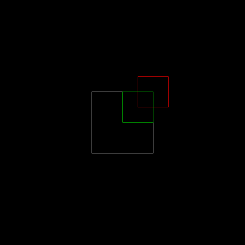
(2) 将立方体的顶点坐标分别沿x,y,z轴方向缩放0.5倍,然后绘制一个白色正方形; (3) 将立方体的顶点坐标分别沿x,y,z轴方向缩放0.5倍,再分别向x,y,z轴正方向平移0.5个单位距离,然后绘制一个红色正方形; (4) 将立方体的顶点坐标分别向x,y,z轴正方向平移0.5个单位距离,再分别沿x,y,z轴方向缩放0.5倍,然后绘制一个绿色正方形。
3. 输出
具体结果如下图所示:
#include <vector>
#include <cmath>
#include <algorithm>
#include <iostream>
#include "model.h"
#include "geometry.h"
#include "pngimage.h"using namespace std;
const double PI = acos(-1.0);void line(Vec3i p0, Vec3i p1, PNGImage  &image, PNGColor color)
{bool steep = false;if (std::abs(p0.x - p1.x) < std::abs(p0.y - p1.y)){std::swap(p0.x, p0.y);std::swap(p1.x, p1.y);steep = true;}if (p0.x > p1.x){std::swap(p0.x, p1.x);std::swap(p0.y, p1.y);}int dx = p1.x - p0.x;int dy = std::abs(p1.y - p0.y);int y = p0.y;int d = -dx;for (int x = p0.x; x <= p1.x; x++){if (steep)image.set(y, x, color);elseimage.set(x, y, color);d = d + 2 * dy;if (d > 0){y += (p1.y > p0.y ? 1 : -1);d = d - 2 * dx;}}
}Matrix viewport(int x, int y, int w, int h, int depth) {Matrix m = Matrix::identity(4);m[0][3] = x + w / 2.f;m[1][3] = y + h / 2.f;m[2][3] = depth / 2.f;m[0][0] = w / 2.f;m[1][1] = h / 2.f;m[2][2] = depth / 2.f;return m;
}Matrix translation(Vec3f v) {Matrix Tr = Matrix::identity(4);Tr[0][3] = v.x;Tr[1][3] = v.y;Tr[2][3] = v.z;return Tr;
}Matrix scale(float factorX, float factorY, float factorZ)
{Matrix Z = Matrix::identity(4);Z[0][0] = factorX;Z[1][1] = factorY;Z[2][2] = factorZ;return Z;
}Matrix rotation_x(float angle)
{angle = angle * PI / 180;float sinangle = sin(angle);float cosangle = cos(angle);Matrix R = Matrix::identity(4);R[1][1] = R[2][2] = cosangle;R[1][2] = -sinangle;R[2][1] = sinangle;return R;
}Matrix rotation_y(float angle)
{angle = angle * PI / 180;float sinangle = sin(angle);float cosangle = cos(angle);Matrix R = Matrix::identity(4);R[0][0] = R[2][2] = cosangle;R[0][2] = sinangle;R[2][0] = -sinangle;return R;
}Matrix rotation_z(float angle) {angle = angle * PI / 180;float sinangle = sin(angle);float cosangle = cos(angle);Matrix R = Matrix::identity(4);R[0][0] = R[1][1] = cosangle;R[0][1] = -sinangle;R[1][0] = sinangle;return R;
}int main(int argc, char** argv)
{const PNGColor white = PNGColor(255, 255, 255, 255);const PNGColor black = PNGColor(0, 0, 0, 255);const PNGColor red = PNGColor(255, 0, 0, 255);const PNGColor green = PNGColor(0, 255, 0, 255);const PNGColor blue = PNGColor(0, 0, 255, 255);const PNGColor yellow = PNGColor(255, 255, 0, 255);Model *model = NULL;const int width = 500;const int height = 500;const int depth = 255;//generate some imagePNGImage image(width, height, PNGImage::RGBA); //Error when RGB because lodepng_get_raw_size_lct(w, h, colortype, bitdepth) > in.size() in encodeimage.init(black);model = new Model("cube.obj");Matrix VP = viewport(width / 4, width / 4, width / 2, height / 2, depth);for (int i = 0; i < model->nfaces(); i++){std::vector<int> face = model->face(i);for (int j = 0; j < (int)face.size(); j++){Vec3f wp0 = model->vert(face[j]);Vec3f wp1 = model->vert(face[(j + 1) % face.size()]);// Please add the code here/********** Begin ********/Matrix S0 = scale(0.5, 0.5, 0.5);Vec3f swp0 = S0 * wp0;Vec3f swp1 = S0 * wp1;// draw the model after scaledVec3f op0 = VP * swp0;Vec3f op1 = VP * swp1;line(op0, op1, image, white);Matrix T = translation(Vec3f(0.5, 0.5, 0.5));Matrix S = scale(0.5, 0.5, 0.5);// scaled then translatedVec3f tsp0 = VP*T*S*swp0;Vec3f tsp1 = VP*T*S*swp1;line(tsp0, tsp1, image, red);// translated then scaledVec3f stp0 = VP*S*T*swp0;Vec3f stp1 = VP*S*T*swp1;line(stp0, stp1, image, green);/********** End *********/}}image.flip_vertically(); // i want to have the origin at the left bottom corner of the imageimage.write_png_file("../img_step2/test.png");delete model;return 0;
}
第3关:图形的平移与旋转
一. 任务描述
1. 本关任务
(1) 理解几何变换基本原理, 掌握平移和旋转变换的方法; (2) 根据几何变换基本原理,将main函数中的空白部分补充完整。
2. 输入
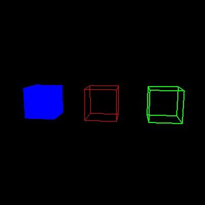
(1) 代码将自动输入一个边长为2的obj正方体模型,具体模型如下图:
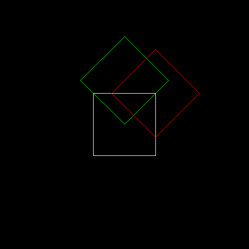
(2) 将立方体的顶点坐标分别沿x,y,z轴方向缩放0.5倍,然后绘制一个白色正方形; (3) 将立方体的顶点坐标分别向x,y,z轴正方向平移0.5个单位距离,再沿z轴逆时针方向旋转45度,然后绘制一个绿色正方形 (4) 将立方体的顶点坐标分别沿z轴逆时针方向旋转45度,再分别向x,y,z轴正方向平移0.5个单位距离,然后绘制一个红色正方形;
3. 输出
具体结果如下图所示:
#include <vector>
#include <cmath>
#include <algorithm>
#include <iostream>
#include "model.h"
#include "geometry.h"
#include "pngimage.h"using namespace std;
const double PI = acos(-1.0);void line(Vec3i p0, Vec3i p1, PNGImage  &image, PNGColor color)
{bool steep = false;if (std::abs(p0.x - p1.x) < std::abs(p0.y - p1.y)){std::swap(p0.x, p0.y);std::swap(p1.x, p1.y);steep = true;}if (p0.x > p1.x){std::swap(p0.x, p1.x);std::swap(p0.y, p1.y);}int dx = p1.x - p0.x;int dy = std::abs(p1.y - p0.y);int y = p0.y;int d = -dx;for (int x = p0.x; x <= p1.x; x++){if (steep)image.set(y, x, color);elseimage.set(x, y, color);d = d + 2 * dy;if (d > 0){y += (p1.y > p0.y ? 1 : -1);d = d - 2 * dx;}}
}Matrix viewport(int x, int y, int w, int h, int depth) {Matrix m = Matrix::identity(4);m[0][3] = x + w / 2.f;m[1][3] = y + h / 2.f;m[2][3] = depth / 2.f;m[0][0] = w / 2.f;m[1][1] = h / 2.f;m[2][2] = depth / 2.f;return m;
}Matrix translation(Vec3f v) {Matrix Tr = Matrix::identity(4);Tr[0][3] = v.x;Tr[1][3] = v.y;Tr[2][3] = v.z;return Tr;
}Matrix scale(float factorX, float factorY, float factorZ)
{Matrix Z = Matrix::identity(4);Z[0][0] = factorX;Z[1][1] = factorY;Z[2][2] = factorZ;return Z;
}Matrix rotation_x(float angle)
{angle = angle * PI / 180;float sinangle = sin(angle);float cosangle = cos(angle);Matrix R = Matrix::identity(4);R[1][1] = R[2][2] = cosangle;R[1][2] = -sinangle;R[2][1] = sinangle;return R;
}Matrix rotation_y(float angle)
{angle = angle * PI / 180;float sinangle = sin(angle);float cosangle = cos(angle);Matrix R = Matrix::identity(4);R[0][0] = R[2][2] = cosangle;R[0][2] = sinangle;R[2][0] = -sinangle;return R;
}Matrix rotation_z(float angle) {angle = angle * PI / 180;float sinangle = sin(angle);float cosangle = cos(angle);Matrix R = Matrix::identity(4);R[0][0] = R[1][1] = cosangle;R[0][1] = -sinangle;R[1][0] = sinangle;return R;
}int main(int argc, char** argv)
{const PNGColor white = PNGColor(255, 255, 255, 255);const PNGColor black = PNGColor(0, 0, 0, 255);const PNGColor red = PNGColor(255, 0, 0, 255);const PNGColor green = PNGColor(0, 255, 0, 255);const PNGColor blue = PNGColor(0, 0, 255, 255);const PNGColor yellow = PNGColor(255, 255, 0, 255);Model *model = NULL;const int width = 500;const int height = 500;const int depth = 255;//generate some imagePNGImage image(width, height, PNGImage::RGBA); //Error when RGB because lodepng_get_raw_size_lct(w, h, colortype, bitdepth) > in.size() in encodeimage.init(black);model = new Model("cube.obj");Matrix VP = viewport(width / 4, width / 4, width / 2, height / 2, depth);for (int i = 0; i < model->nfaces(); i++){std::vector<int> face = model->face(i);for (int j = 0; j < (int)face.size(); j++){Vec3f wp0 = model->vert(face[j]);Vec3f wp1 = model->vert(face[(j + 1) % face.size()]);// Please add the code here/********** Begin ********/Matrix S = scale(0.5,0.5,0.5);Vec3f sp0 = VP*S*wp0;Vec3f sp1 = VP*S*wp1;line(sp0,sp1,image,white);Matrix P = rotation_z(45)*translation(Vec3f(0.5,0.5,0.5))*S;Vec3f pp0 = VP*P*wp0;Vec3f pp1 = VP*P*wp1;line(pp0,pp1,image,green);Matrix Q = translation(Vec3f(0.5,0.5,0.5))*rotation_z(45)*S;Vec3f qp0 = VP*Q*wp0;Vec3f qp1 = VP*Q*wp1;line(qp0,qp1,image,red);/********** End *********/}}image.flip_vertically(); // i want to have the origin at the left bottom corner of the imageimage.write_png_file("../img_step1/test.png");delete model;return 0;
}
第4关:图形的旋转与缩放
一. 任务描述
1. 本关任务
(1) 理解几何变换基本原理, 掌握旋转和缩放变换的方法; (2) 根据几何变换基本原理,将main函数中的空白部分补充完整。
2. 输入
(1) 代码将自动输入一个边长为2的obj正方体模型,具体模型如下图:
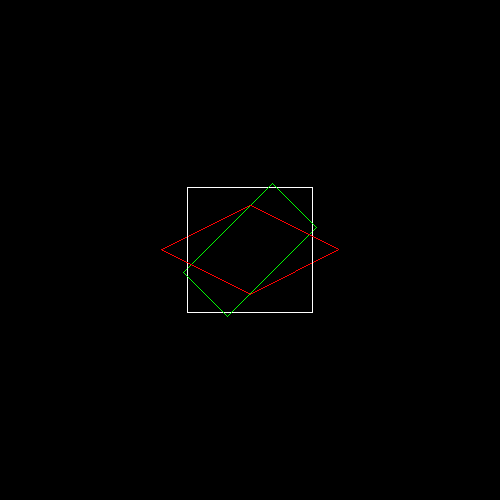
(2) 将立方体的顶点坐标分别沿x,y,z轴方向缩放0.5倍,然后绘制一个白色正方形; (3) 将立方体的顶点坐标分别向y,z轴缩放0.5倍,x轴保持不变,再沿z轴逆时针方向旋转45度,然后绘制一个绿色矩形; (4) 将立方体的顶点坐标分别沿z轴逆时针方向旋转45度,再分别向y,z轴缩放0.5倍,x轴保持不变,然后绘制一个红菱形。
3. 输出
具体结果如下图所示:
#include <vector>
#include <cmath>
#include <algorithm>
#include <iostream>
#include "model.h"
#include "geometry.h"
#include "pngimage.h"using namespace std;
const double PI = acos(-1.0);void line(Vec3i p0, Vec3i p1, PNGImage  &image, PNGColor color)
{bool steep = false;if (std::abs(p0.x - p1.x) < std::abs(p0.y - p1.y)){std::swap(p0.x, p0.y);std::swap(p1.x, p1.y);steep = true;}if (p0.x > p1.x){std::swap(p0.x, p1.x);std::swap(p0.y, p1.y);}int dx = p1.x - p0.x;int dy = std::abs(p1.y - p0.y);int y = p0.y;int d = -dx;for (int x = p0.x; x <= p1.x; x++){if (steep)image.set(y, x, color);elseimage.set(x, y, color);d = d + 2 * dy;if (d > 0){y += (p1.y > p0.y ? 1 : -1);d = d - 2 * dx;}}
}Matrix viewport(int x, int y, int w, int h, int depth) {Matrix m = Matrix::identity(4);m[0][3] = x + w / 2.f;m[1][3] = y + h / 2.f;m[2][3] = depth / 2.f;m[0][0] = w / 2.f;m[1][1] = h / 2.f;m[2][2] = depth / 2.f;return m;
}Matrix translation(Vec3f v) {Matrix Tr = Matrix::identity(4);Tr[0][3] = v.x;Tr[1][3] = v.y;Tr[2][3] = v.z;return Tr;
}Matrix scale(float factorX, float factorY, float factorZ)
{Matrix Z = Matrix::identity(4);Z[0][0] = factorX;Z[1][1] = factorY;Z[2][2] = factorZ;return Z;
}Matrix rotation_x(float angle)
{angle = angle * PI / 180;float sinangle = sin(angle);float cosangle = cos(angle);Matrix R = Matrix::identity(4);R[1][1] = R[2][2] = cosangle;R[1][2] = -sinangle;R[2][1] = sinangle;return R;
}Matrix rotation_y(float angle)
{angle = angle * PI / 180;float sinangle = sin(angle);float cosangle = cos(angle);Matrix R = Matrix::identity(4);R[0][0] = R[2][2] = cosangle;R[0][2] = sinangle;R[2][0] = -sinangle;return R;
}Matrix rotation_z(float angle) {angle = angle * PI / 180;float sinangle = sin(angle);float cosangle = cos(angle);Matrix R = Matrix::identity(4);R[0][0] = R[1][1] = cosangle;R[0][1] = -sinangle;R[1][0] = sinangle;return R;
}int main(int argc, char** argv)
{const PNGColor white = PNGColor(255, 255, 255, 255);const PNGColor black = PNGColor(0, 0, 0, 255);const PNGColor red = PNGColor(255, 0, 0, 255);const PNGColor green = PNGColor(0, 255, 0, 255);const PNGColor blue = PNGColor(0, 0, 255, 255);const PNGColor yellow = PNGColor(255, 255, 0, 255);Model *model = NULL;const int width = 500;const int height = 500;const int depth = 255;//generate some imagePNGImage image(width, height, PNGImage::RGBA); //Error when RGB because lodepng_get_raw_size_lct(w, h, colortype, bitdepth) > in.size() in encodeimage.init(black);model = new Model("cube.obj");Matrix VP = viewport(width / 4, width / 4, width / 2, height / 2, depth);for (int i = 0; i < model->nfaces(); i++){std::vector<int> face = model->face(i);for (int j = 0; j < (int)face.size(); j++){Vec3f wp0 = model->vert(face[j]);Vec3f wp1 = model->vert(face[(j + 1) % face.size()]);// Please add the code here/********** Begin ********/Matrix S = scale(0.5,0.5,0.5);Vec3f sp0 = VP*S*wp0;Vec3f sp1 = VP*S*wp1;line(sp0,sp1,image,white);Matrix P = rotation_z(45)*scale(1,0.5,0.5)*S;Vec3f pp0 = VP*P*wp0;Vec3f pp1 = VP*P*wp1;line(pp0,pp1,image,green);Matrix Q = scale(1,0.5,0.5)*rotation_z(45)*S;Vec3f qp0 = VP*Q*wp0;Vec3f qp1 = VP*Q*wp1;line(qp0,qp1,image,red);/********** End *********/}}image.flip_vertically(); // i want to have the origin at the left bottom corner of the imageimage.write_png_file("../img_step4/test.png");delete model;return 0;
}
第5关:绘制三菱形状
一. 任务描述
1. 本关任务
(1) 理解几何变换基本原理, 掌握平移、旋转和缩放变换的方法; (2) 根据几何变换基本原理,将main函数中的空白部分补充完整来绘制三菱形状。
2. 输入
(1) 代码将自动输入一个边长为2的obj正方体模型,具体模型如下图:
(2) 将立方体的顶点坐标分别沿x,y,z轴方向缩放0.5倍; (3) 将立方体的顶点坐标分别沿z轴逆时针方向旋转45度,再分别向y,z轴缩放0.5倍,x轴保持不变,然后绘制一个红菱形; (4) 将红色菱形沿着x轴正方向平移
22个单位距离,然后将红菱形沿Z轴逆时针旋转90度; (5)绿色和黄色菱形与红色菱形的夹角均为120度。3. 输出
具体结果如下图所示:
#include <vector>
#include <cmath>
#include <algorithm>
#include <iostream>
#include "model.h"
#include "geometry.h"
#include "pngimage.h"using namespace std;
const double PI = acos(-1.0);void line(Vec3i p0, Vec3i p1, PNGImage  &image, PNGColor color)
{bool steep = false;if (std::abs(p0.x - p1.x) < std::abs(p0.y - p1.y)){std::swap(p0.x, p0.y);std::swap(p1.x, p1.y);steep = true;}if (p0.x > p1.x){std::swap(p0.x, p1.x);std::swap(p0.y, p1.y);}int dx = p1.x - p0.x;int dy = std::abs(p1.y - p0.y);int y = p0.y;int d = -dx;for (int x = p0.x; x <= p1.x; x++){if (steep)image.set(y, x, color);elseimage.set(x, y, color);d = d + 2 * dy;if (d > 0){y += (p1.y > p0.y ? 1 : -1);d = d - 2 * dx;}}
}Matrix viewport(int x, int y, int w, int h, int depth) {Matrix m = Matrix::identity(4);m[0][3] = x + w / 2.f;m[1][3] = y + h / 2.f;m[2][3] = depth / 2.f;m[0][0] = w / 2.f;m[1][1] = h / 2.f;m[2][2] = depth / 2.f;return m;
}Matrix translation(Vec3f v) {Matrix Tr = Matrix::identity(4);Tr[0][3] = v.x;Tr[1][3] = v.y;Tr[2][3] = v.z;return Tr;
}Matrix scale(float factorX, float factorY, float factorZ)
{Matrix Z = Matrix::identity(4);Z[0][0] = factorX;Z[1][1] = factorY;Z[2][2] = factorZ;return Z;
}Matrix rotation_x(float angle)
{angle = angle * PI / 180;float sinangle = sin(angle);float cosangle = cos(angle);Matrix R = Matrix::identity(4);R[1][1] = R[2][2] = cosangle;R[1][2] = -sinangle;R[2][1] = sinangle;return R;
}Matrix rotation_y(float angle)
{angle = angle * PI / 180;float sinangle = sin(angle);float cosangle = cos(angle);Matrix R = Matrix::identity(4);R[0][0] = R[2][2] = cosangle;R[0][2] = sinangle;R[2][0] = -sinangle;return R;
}Matrix rotation_z(float angle) {angle = angle * PI / 180;float sinangle = sin(angle);float cosangle = cos(angle);Matrix R = Matrix::identity(4);R[0][0] = R[1][1] = cosangle;R[0][1] = -sinangle;R[1][0] = sinangle;return R;
}int main(int argc, char** argv)
{const PNGColor white = PNGColor(255, 255, 255, 255);const PNGColor black = PNGColor(0, 0, 0, 255);const PNGColor red = PNGColor(255, 0, 0, 255);const PNGColor green = PNGColor(0, 255, 0, 255);const PNGColor blue = PNGColor(0, 0, 255, 255);const PNGColor yellow = PNGColor(255, 255, 0, 255);Model *model = NULL;const int width = 800;const int height = 800;const int depth = 255;//generate some imagePNGImage image(width, height, PNGImage::RGBA); //Error when RGB because lodepng_get_raw_size_lct(w, h, colortype, bitdepth) > in.size() in encodeimage.init(black);model = new Model("cube.obj");Matrix VP = viewport(width / 4, width / 4, width / 2, height / 2, depth);for (int i = 0; i < model->nfaces(); i++){std::vector<int> face = model->face(i);for (int j = 0; j < (int)face.size(); j++){Vec3f wp0 = model->vert(face[j]);Vec3f wp1 = model->vert(face[(j + 1) % face.size()]);Matrix T = translation(Vec3f(sqrt(2)/2, 0, 0));// Please add the code here/********** Begin ********/Matrix S = scale(0.5f,0.5f  ,0.5f  );Matrix S1 = scale(1.f,0.5f  ,0.5f  );Matrix R = rotation_z(45.f);Matrix R3 = rotation_z(90.f);Matrix R2 = rotation_z(120.f);Matrix R1 = rotation_z(-120.f);Vec3f sp0 = VP*R3*T*S1*R*S*wp0;Vec3f sp1 = VP*R3*T*S1*R*S*wp1;line(sp0, sp1, image, red);Vec3f op0 = VP*R2*R3*T*S1*R*S*wp0;Vec3f op1 = VP*R2*R3*T*S1*R*S*wp1;line(op0, op1, image,green );Vec3f Sp0 = VP*R1*R3*T*S1*R*S*wp0;Vec3f Sp1 = VP*R1*R3*T*S1*R*S*wp1;line(Sp0, Sp1, image,yellow );/********** End *********/}		}image.flip_vertically(); // i want to have the origin at the left bottom corner of the imageimage.write_png_file("../img_step5/test.png");delete model;return 0;
}
模型、观察及视口变换v1.0
第1关:立方体模型变换
一.任务描述
根据提示,在右侧修改代码,并自己绘制出图形。平台会对你编写的代码进行测试。
1.本关任务
学习了解三维图形几何变换原理。 理解掌握OpenGL三维图形几何变换的方法。 理解掌握OpenGL程序的模型视图变换。 掌握OpenGL三维图形显示与观察的原理与实现。
2.预期输出
3.具体要求
(1).背景色为黑色,用 glclearcolor 来完成;
(2).运用glPushMatrix()函数和glPopMatrix()函数进行矩阵操作,以中心为绘制原点,设置前景色为红色glColor3f(1.0, 0.0, 0.0),绘制单位立方体线框,用glutWireCube(1.0)完成;
(3).运用glPushMatrix()函数和glPopMatrix()函数进行矩阵操作,设置前景色为黑色glColor3f(0.0, 1.0, 0.0),设置线宽为2.0用glLineWidth(2.0)完成,将原单位立方体线框沿X轴正方向平移2.0;
(4).运用glPushMatrix()函数和glPopMatrix()函数进行矩阵操作,沿X轴负方向平移2.0,设置前景色为蓝色glColor3f(0.0, 0.0, 1.0),绘制单位立方体实体用glutSolidCube(1.0)完成;
// 提示:在合适的地方修改或添加代码
#include <GL/freeglut.h>
#include<stdio.h>// 评测代码所用头文件-开始
#include<opencv2/core/core.hpp>
#include<opencv2/highgui/highgui.hpp>
#include<opencv2/imgproc/imgproc.hpp>
// 评测代码所用头文件-结束GLint winWidth = 400, winHeight =400 ; 	      //设置初始化窗口大小/*观察坐标系参数设置*/
GLfloat x0 = 0.0, yy = 0.0, z0 = 5.0;	   //设置观察坐标系原点
GLfloat xref = 0.0, yref = 0.0, zref = 0.0;	//设置观察坐标系参考点(视点)
GLfloat Vx = 0.0, Vy = 1.0, Vz = 0.0;	   //设置观察坐标系向上向量(y轴) /*观察体参数设置 */
GLfloat xwMin = -1.0, ywMin = -1.0, xwMax = 1.0, ywMax = 1.0;//设置裁剪窗口坐标范围
GLfloat dnear = 1.5, dfar = 20.0;	      //设置远、近裁剪面深度范围void init(void)
{glClearColor(0.0, 0.0, 0.0, 0.0);
}
void display(void)
{glClear(GL_COLOR_BUFFER_BIT);glLoadIdentity();/*观察变换*/gluLookAt(x0, yy, z0, xref, yref, zref, Vx, Vy, Vz);        //指定三维观察参数// 请在此添加你的代码/********** Begin ********///glColor3f(1.0, 0.0, 0.0);glPushMatrix();glutWireCube(1.0);glPopMatrix();
//glColor3f(0.0, 1.0, 0.0);glLineWidth(2.0);glPushMatrix();glTranslatef(2.0f,0.0f,0.0f);glutWireCube(1.0);glPopMatrix();
//glColor3f(0.0, 0.0, 1.0);glPushMatrix();glTranslatef(-2.0f,0.0f,0.0f);glutSolidCube(1.0);glPopMatrix();/********** End **********/glFlush();
}void reshape(GLint newWidth, GLint newHeight)
{/*视口变换*/glViewport(0, 0, newWidth, newHeight);	//定义视口大小/*投影变换*/glMatrixMode(GL_PROJECTION);glLoadIdentity();/*透视投影,设置透视观察体*/glFrustum(xwMin, xwMax, ywMin, ywMax, dnear, dfar);/*模型变换*/glMatrixMode(GL_MODELVIEW);winWidth = newWidth;winHeight = newHeight;
}
int main(int argc, char* argv[])
{glutInit(&argc, argv);glutInitWindowPosition(100, 100);glutInitWindowSize( 400 , 400 );        //设置初始化窗口大小glutCreateWindow("三维观察");init();glutDisplayFunc(display);glutReshapeFunc(reshape);glutMainLoopEvent();/*************以下为评测代码,与本次实验内容无关,请勿修改**************/GLubyte* pPixelData = (GLubyte*)malloc(800 * 400 * 3);//分配内存GLint viewport[4] = { 0 };glReadBuffer(GL_FRONT);glPixelStorei(GL_UNPACK_ALIGNMENT, 4);glGetIntegerv(GL_VIEWPORT, viewport);glReadPixels(viewport[0], viewport[1], viewport[2], viewport[3], GL_RGB, GL_UNSIGNED_BYTE, pPixelData);cv::Mat img;std::vector<cv::Mat> imgPlanes;img.create(400, 400, CV_8UC3);cv::split(img, imgPlanes);for (int i = 0; i < 400; i++) {unsigned char* plane0Ptr = imgPlanes[0].ptr<unsigned char>(i);unsigned char* plane1Ptr = imgPlanes[1].ptr<unsigned char>(i);unsigned char* plane2Ptr = imgPlanes[2].ptr<unsigned char>(i);for (int j = 0; j < 400; j++) {int k = 3 * (i * 400 + j);plane2Ptr[j] = pPixelData[k];plane1Ptr[j] = pPixelData[k + 1];plane0Ptr[j] = pPixelData[k + 2];}}cv::merge(imgPlanes, img);cv::flip(img, img, 0);cv::namedWindow("openglGrab");cv::imshow("openglGrab", img);//cv::waitKey();cv::imwrite("../img_step1/test.jpg", img);return 0;
}
第2关:立方体观察变换
一.任务描述
根据提示,在右侧修改代码,并自己绘制出图形。平台会对你编写的代码进行测试。
1.本关任务
学习了解三维图形几何变换原理。 理解掌握OpenGL三维图形几何变换的方法。 理解掌握OpenGL程序的模型视图变换。 掌握OpenGL三维图形显示与观察的原理与实现。
2.预期输出
3.具体要求
(1).背景色为黑色,用 glclearcolor 来完成;
(2).运用glPushMatrix()函数和glPopMatrix()函数进行矩阵操作,以中心为绘制原点,设置前景色为红色glColor3f(1.0, 0.0, 0.0),绘制单位立方体线框,用glutWireCube(1.0)完成;
(3).运用glPushMatrix()函数和glPopMatrix()函数进行矩阵操作,设置前景色为黑色glColor3f(0.0, 1.0, 0.0),设置线宽为2.0用glLineWidth(2.0)完成,将原单位立方体线框沿X轴正方向平移2.0;
(4).运用glPushMatrix()函数和glPopMatrix()函数进行矩阵操作,沿X轴负方向平移2.0,设置前景色为蓝色glColor3f(0.0, 0.0, 1.0),绘制单位立方体实体用glutSolidCube(1.0)完成;(5).视点改为(1.0,1.5,8.0),观察中心改为在(0, 0 ,0),向上矢量改为(0, 1, 0);
(6).将glFrustum(xwMin, xwMax, ywMin, ywMax, dnear, dfar);换为透视投影gluPerspective (fovy,aspect,zNear,zFar)函数,参数分别为(视角,宽高比,近处,远处)。要求参数为gluPerspective(45, 1, 1, 100)。
// 提示:在合适的地方修改或添加代码
#include <GL/freeglut.h>
#include<stdio.h>// 评测代码所用头文件-开始
#include<opencv2/core/core.hpp>
#include<opencv2/highgui/highgui.hpp>
#include<opencv2/imgproc/imgproc.hpp>
// 评测代码所用头文件-结束GLint winWidth = 400, winHeight =400 ;           //设置初始化窗口大小/*观察坐标系参数设置*/
GLfloat x0 = 1.0, yy = 1.5, z0 = 8.0;       //设置观察坐标系原点
GLfloat xref = 0.0, yref = 0.0, zref = 0.0;    //设置观察坐标系参考点(视点)
GLfloat Vx = 0.0, Vy = 1.0, Vz = 0.0;       //设置观察坐标系向上向量(y轴) /*观察体参数设置 */
GLfloat xwMin = -1.0, ywMin = -1.0, xwMax = 1.0, ywMax = 1.0;//设置裁剪窗口坐标范围
GLfloat dnear = 1.5, dfar = 20.0;          //设置远、近裁剪面深度范围void init(void)
{glClearColor(0.0, 0.0, 0.0, 0.0);
}
void display(void)
{glClear(GL_COLOR_BUFFER_BIT);glLoadIdentity();/*观察变换*/gluLookAt(x0, yy, z0, xref, yref, zref, Vx, Vy, Vz);        //指定三维观察参数// 请在此添加你的代码/********** Begin ********/glPushMatrix();glColor3f(1.0, 0.0, 0.0);glutWireCube(1.0);glPopMatrix();glPushMatrix();glColor3f(0.0, 1.0, 0.0);glLineWidth(2.0);glTranslatef(2.0f,0.0f,0.0f);glutWireCube(1.0);glPopMatrix();glPushMatrix();glColor3f(0.0, 0.0, 1.0);glLineWidth(2.0);glTranslatef(-2.0f,0.0f,0.0f);glutSolidCube(1.0);glPopMatrix();/********** End **********/glFlush();
}
void reshape(GLint newWidth, GLint newHeight)
{/*视口变换*/glViewport(0, 0, newWidth, newHeight);    //定义视口大小/*投影变换*/glMatrixMode(GL_PROJECTION);glLoadIdentity();/*透视投影,设置透视观察体*/gluPerspective( 45,1,1,100 );/*模型变换*/glMatrixMode(GL_MODELVIEW);winWidth = newWidth;winHeight = newHeight;
}
int main(int argc, char* argv[])
{glutInit(&argc, argv);glutInitWindowPosition(100, 100);glutInitWindowSize( 400 , 400 );        //设置初始化窗口大小glutCreateWindow("三维观察");init();glutDisplayFunc(display);glutReshapeFunc(reshape);glutMainLoopEvent();/*************以下为评测代码,与本次实验内容无关,请勿修改**************/GLubyte* pPixelData = (GLubyte*)malloc(800 * 400 * 3);//分配内存GLint viewport[4] = { 0 };   glReadBuffer(GL_FRONT);glPixelStorei(GL_UNPACK_ALIGNMENT, 4);glGetIntegerv(GL_VIEWPORT, viewport);glReadPixels(viewport[0], viewport[1], viewport[2], viewport[3], GL_RGB, GL_UNSIGNED_BYTE, pPixelData);cv::Mat img;std::vector<cv::Mat> imgPlanes;img.create(400, 400, CV_8UC3);cv::split(img, imgPlanes);for (int i = 0; i < 400; i++) {unsigned char* plane0Ptr = imgPlanes[0].ptr<unsigned char>(i);unsigned char* plane1Ptr = imgPlanes[1].ptr<unsigned char>(i);unsigned char* plane2Ptr = imgPlanes[2].ptr<unsigned char>(i);for (int j = 0; j < 400; j++) {int k = 3 * (i * 400 + j);plane2Ptr[j] = pPixelData[k];plane1Ptr[j] = pPixelData[k + 1];plane0Ptr[j] = pPixelData[k + 2];}}cv::merge(imgPlanes, img);cv::flip(img, img, 0);cv::namedWindow("openglGrab");cv::imshow("openglGrab", img);//cv::waitKey();cv::imwrite("../img_step2/test.jpg", img);return 0;
}
第3关:立方体视口变换
一.任务描述
根据提示,在右侧修改代码,并自己绘制出图形。平台会对你编写的代码进行测试。
1.本关任务
学习了解三维图形几何变换原理。 理解掌握OpenGL三维图形几何变换的方法。 理解掌握OpenGL程序的模型视图变换。 掌握OpenGL三维图形显示与观察的原理与实现。
2.预期输出
3.具体要求
(1).背景色为黑色,用 glclearcolor 来完成;
(2).运用glPushMatrix()函数和glPopMatrix()函数进行矩阵操作,以中心为绘制原点,设置前景色为红色glColor3f(1.0, 0.0, 0.0),绘制单位立方体线框,用glutWireCube(1.0)完成;
(3).运用glPushMatrix()函数和glPopMatrix()函数进行矩阵操作,设置前景色为黑色glColor3f(0.0, 1.0, 0.0),设置线宽为2.0用glLineWidth(2.0)完成,将原单位立方体线框沿X轴正方向平移2.0;
(4).运用glPushMatrix()函数和glPopMatrix()函数进行矩阵操作,沿X轴负方向右平移2.0,设置前景色为蓝色glColor3f(0.0, 0.0, 1.0),绘制单位立方体实体用glutSolidCube(1.0)完成; (5).进行视口变换视口宽为800,高为400。实验内调整winWidth和winHeight 来设置初始化窗口大小;(6).调用透视投影gluperspective()函数,参数为gluPerspective(45, 2, 1, 100)要求宽高比为2;
(7).在main函数中用glutInitWindowSize()调整视口窗口大小。
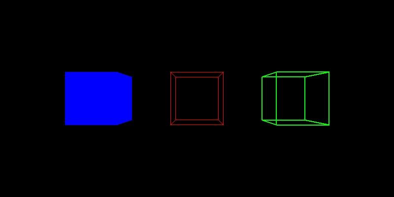
// 提示:在合适的地方修改或添加代码
#include <GL/freeglut.h>
#include<stdio.h>// 评测代码所用头文件-开始
#include<opencv2/core/core.hpp>
#include<opencv2/highgui/highgui.hpp>
#include<opencv2/imgproc/imgproc.hpp>
// 评测代码所用头文件-结束GLint winWidth =800 , winHeight =400 ; 	      //设置初始化窗口大小/*观察坐标系参数设置*/
GLfloat x0 = 0.0, yy = 0.0, z0 = 5.0;	   //设置观察坐标系原点
GLfloat xref = 0.0, yref = 0.0, zref = 0.0;	//设置观察坐标系参考点(视点)
GLfloat Vx = 0.0, Vy = 1.0, Vz = 0.0;	   //设置观察坐标系向上向量(y轴) /*观察体参数设置 */
GLfloat xwMin = -1.0, ywMin = -1.0, xwMax = 1.0, ywMax = 1.0;//设置裁剪窗口坐标范围
GLfloat dnear = 1.5, dfar = 20.0;	      //设置远、近裁剪面深度范围void init(void)
{glClearColor(0.0, 0.0, 0.0, 0.0);
}
void display(void)
{glClear(GL_COLOR_BUFFER_BIT);glLoadIdentity();/*观察变换*/gluLookAt(x0, yy, z0, xref, yref, zref, Vx, Vy, Vz);        //指定三维观察参数// 请在此添加你的代码/********** Begin ********/glColor3f(1.0, 0.0, 0.0);glPushMatrix();glutWireCube(1.0);glPopMatrix();glColor3f(0.0, 1.0, 0.0);glLineWidth(2.0);glPushMatrix();glTranslatef(2.0f,0.0f,0.0f);glutWireCube(1.0);glPopMatrix();glColor3f(0.0, 0.0, 1.0);glPushMatrix();glTranslatef(-2.0f,0.0f,0.0f);glutSolidCube(1.0);glPopMatrix();/********** End **********/glFlush();
}void reshape(GLint newWidth, GLint newHeight)
{/*视口变换*/glViewport(0, 0, newWidth, newHeight);	//定义视口大小/*投影变换*/glMatrixMode(GL_PROJECTION);glLoadIdentity();/*透视投影,设置透视观察体*/gluPerspective( 45,2 ,1 ,100 );/*模型变换*/glMatrixMode(GL_MODELVIEW);winWidth = newWidth;winHeight = newHeight;
}
int main(int argc, char* argv[])
{glutInit(&argc, argv);glutInitWindowPosition(100, 100);glutInitWindowSize( 800 ,400  );        //设置初始化窗口大小glutCreateWindow("三维观察");init();glutDisplayFunc(display);glutReshapeFunc(reshape);glutMainLoopEvent();/*************以下为评测代码,与本次实验内容无关,请勿修改**************/GLubyte* pPixelData = (GLubyte*)malloc(800 * 400 * 3);//分配内存GLint viewport[4] = { 0 }; glReadBuffer(GL_FRONT);glPixelStorei(GL_UNPACK_ALIGNMENT, 4);glGetIntegerv(GL_VIEWPORT, viewport);glReadPixels(viewport[0], viewport[1], viewport[2], viewport[3], GL_RGB, GL_UNSIGNED_BYTE, pPixelData);cv::Mat img;std::vector<cv::Mat> imgPlanes;img.create(400, 800, CV_8UC3);cv::split(img, imgPlanes);for (int i = 0; i < 400; i++) {unsigned char* plane0Ptr = imgPlanes[0].ptr<unsigned char>(i);unsigned char* plane1Ptr = imgPlanes[1].ptr<unsigned char>(i);unsigned char* plane2Ptr = imgPlanes[2].ptr<unsigned char>(i);for (int j = 0; j < 800; j++) {int k = 3 * (i * 800 + j);plane2Ptr[j] = pPixelData[k];plane1Ptr[j] = pPixelData[k + 1];plane0Ptr[j] = pPixelData[k + 2];}}cv::merge(imgPlanes, img);cv::flip(img, img, 0);cv::namedWindow("openglGrab");cv::imshow("openglGrab", img);//cv::waitKey();cv::imwrite("../img_step5/test.jpg", img);return 0;
}
模型、观察及视口变换v2.0
第1关:模型变换-左右两个立方体
一. 任务描述
1. 本关任务
(1) 理解模型变换基本原理,掌握平移和旋转变换的方法; (2) 根据模型变换基本原理,将main函数中的空白部分补充完整。
2. 输入
(1) 代码将自动输入一个边长为1的obj正方体模型,具体模型如下图:
(2) 代码自动将模型投影到二维平面上生成一个边长为1的白色立方体,具体图片如下所示:
(3) 将白色立方体的顶点坐标向x轴正方向平移1.2个单位距离,然后绘制一个红色立方形; (4) 将白色立方体的顶点坐标沿y轴逆时针方向旋转30度,再向x轴负方向平移1.3个单位距离,然后绘制一个绿色正方形。
3. 输出
具体结果如下图所示:
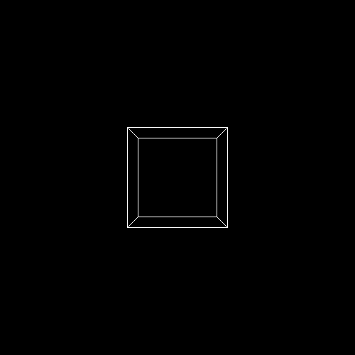
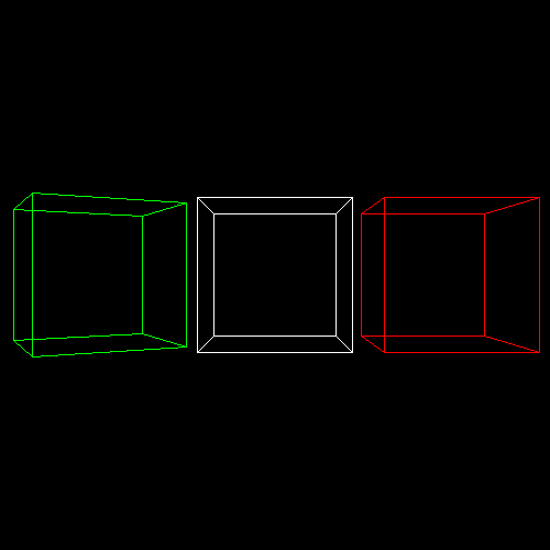
#include <vector>
#include <cmath>
#include <algorithm>
#include <iostream>
#include "model.h"
#include "geometry.h"
#include "pngimage.h"using namespace std;
const double PI = acos(-1.0);void line(Vec3i p0, Vec3i p1, PNGImage  &image, PNGColor color)
{bool steep = false;if (std::abs(p0.x - p1.x) < std::abs(p0.y - p1.y)){std::swap(p0.x, p0.y);std::swap(p1.x, p1.y);steep = true;}if (p0.x > p1.x){std::swap(p0.x, p1.x);std::swap(p0.y, p1.y);}int dx = p1.x - p0.x;int dy = std::abs(p1.y - p0.y);int y = p0.y;int d = -dx;for (int x = p0.x; x <= p1.x; x++){if (steep)image.set(y, x, color);elseimage.set(x, y, color);d = d + 2 * dy;if (d > 0){y += (p1.y > p0.y ? 1 : -1);d = d - 2 * dx;}}
}Matrix translation(Vec3f v) {//平移Matrix Tr = Matrix::identity(4);Tr[0][3] = v.x;Tr[1][3] = v.y;Tr[2][3] = v.z;return Tr;
}Matrix scale(float factorX, float factorY, float factorZ)
{Matrix Z = Matrix::identity(4);Z[0][0] = factorX;Z[1][1] = factorY;Z[2][2] = factorZ;return Z;
}Matrix rotation_x(float angle)
{angle = angle * PI / 180;float sinangle = sin(angle);float cosangle = cos(angle);Matrix R = Matrix::identity(4);R[1][1] = R[2][2] = cosangle;R[1][2] = -sinangle;R[2][1] = sinangle;return R;
}Matrix rotation_y(float angle)
{angle = angle * PI / 180;float sinangle = sin(angle);float cosangle = cos(angle);Matrix R = Matrix::identity(4);R[0][0] = R[2][2] = cosangle;R[0][2] = sinangle;R[2][0] = -sinangle;return R;
}Matrix rotation_z(float angle) {angle = angle * PI / 180;float sinangle = sin(angle);float cosangle = cos(angle);Matrix R = Matrix::identity(4);R[0][0] = R[1][1] = cosangle;R[0][1] = -sinangle;R[1][0] = sinangle;return R;
}int main(int argc, char** argv)
{const PNGColor white = PNGColor(255, 255, 255, 255);const PNGColor black = PNGColor(0, 0, 0, 255);const PNGColor red = PNGColor(255, 0, 0, 255);const PNGColor green = PNGColor(0, 255, 0, 255);const PNGColor blue = PNGColor(0, 0, 255, 255);const PNGColor yellow = PNGColor(255, 255, 0, 255);Model *model = NULL;const int width = 500;const int height = 500;const int depth = 255;Vec3f eye(0.5, 1.5, 4);Vec3f center(0, 0, 0);Matrix Projection = Matrix::projection(eye, center);Matrix ViewPort = Matrix::viewport(width / 4, width / 4, width / 2, height / 2, depth);//generate some imagePNGImage image(width, height, PNGImage::RGBA); //Error when RGB because lodepng_get_raw_size_lct(w, h, colortype, bitdepth) > in.size() in encodeimage.init(black);model = new Model("cube.obj");for (int i = 0; i < model->nfaces(); i++){std::vector<int> face = model->face(i);for (int j = 0; j < (int)face.size(); j++){Vec3f wp0 = model->vert(face[j]);Vec3f wp1 = model->vert(face[(j + 1) % face.size()]);Matrix S0 = scale(0.5, 0.5, 0.5);Vec3f swp0 = S0 * wp0;Vec3f swp1 = S0 * wp1;// for comparing - draw the model after scaled Vec3f op0 = ViewPort * Projection * swp0;Vec3f op1 = ViewPort * Projection * swp1;line(op0, op1, image, white);// Please add the code here/********** Begin ********///3) 将白色立方体的顶点坐标向x轴正方向平移1.2个单位距离,然后绘制一个红色立方形Matrix S1 = translation(Vec3f(1.2,0.0,0.0));op0 = ViewPort * Projection *S1 * swp0;op1 = ViewPort * Projection *S1 * swp1;line(op0, op1, image, red);// (4) 将白色立方体的顶点坐标沿y轴逆时针方向旋转30度,再向x轴负方向平移1.3个单位距离,然后绘制一个绿色正方形//    Matrix rotation_y(float angle)Matrix S3 = rotation_y(30.0);Matrix S4 = translation(Vec3f(-1.3,0.0,0.0));op0 = ViewPort * Projection *S4 *S3 * swp0;op1 = ViewPort * Projection *S4 *S3 * swp1;line(op0, op1, image,green );/********** End *********/}}image.flip_vertically(); // i want to have the origin at the left bottom corner of the imageimage.write_png_file("../img_step1/test.png");delete model;return 0;
}
第2关:观察变换
一. 任务描述
1. 本关任务
(1) 理解观察变换基本原理,将lookat函数中空白部分补充完整; (2) 将main函数中的参数补充完整。
2. 输入
(1) 代码将自动输入一个边长为1的obj正方体模型,具体模型如下图:
(2) 相机坐标为(0, 1.5, 4),中心点坐标为(0,0,0),向上的矢量为Vec3f(0, 1, 0)
3. 输出
具体结果如下图所示:

#include <vector>
#include <cmath>
#include <algorithm>
#include <iostream>
#include "model.h"
#include "geometry.h"
#include "pngimage.h"using namespace std;
const double PI = acos(-1.0);void line(Vec3i p0, Vec3i p1, PNGImage  &image, PNGColor color)
{bool steep = false;if (std::abs(p0.x - p1.x) < std::abs(p0.y - p1.y)){std::swap(p0.x, p0.y);std::swap(p1.x, p1.y);steep = true;}if (p0.x > p1.x){std::swap(p0.x, p1.x);std::swap(p0.y, p1.y);}int dx = p1.x - p0.x;int dy = std::abs(p1.y - p0.y);int y = p0.y;int d = -dx;for (int x = p0.x; x <= p1.x; x++){if (steep)image.set(y, x, color);elseimage.set(x, y, color);d = d + 2 * dy;if (d > 0){y += (p1.y > p0.y ? 1 : -1);d = d - 2 * dx;}}
}Matrix lookat(Vec3f eye, Vec3f center, Vec3f up) {Matrix res = Matrix::identity(4);// Please add the code here/********** Begin ********/Vec3f z = (eye - center).normalize();Vec3f x = (up^z).normalize();Vec3f y = (z^x).normalize();for (int i = 0; i < 3; i++) {res[0][i] = x[i];res[1][i] = y[i];res[2][i] = z[i];res[i][3] = -center[i];}/********** End ********/return res;
}Matrix translation(Vec3f v) {Matrix Tr = Matrix::identity(4);Tr[0][3] = v.x;Tr[1][3] = v.y;Tr[2][3] = v.z;return Tr;
}Matrix scale(float factorX, float factorY, float factorZ)
{Matrix Z = Matrix::identity(4);Z[0][0] = factorX;Z[1][1] = factorY;Z[2][2] = factorZ;return Z;
}Matrix rotation_x(float angle)
{angle = angle * PI / 180;float sinangle = sin(angle);float cosangle = cos(angle);Matrix R = Matrix::identity(4);R[1][1] = R[2][2] = cosangle;R[1][2] = -sinangle;R[2][1] = sinangle;return R;
}Matrix rotation_y(float angle)
{angle = angle * PI / 180;float sinangle = sin(angle);float cosangle = cos(angle);Matrix R = Matrix::identity(4);R[0][0] = R[2][2] = cosangle;R[0][2] = sinangle;R[2][0] = -sinangle;return R;
}Matrix rotation_z(float angle) {angle = angle * PI / 180;float sinangle = sin(angle);float cosangle = cos(angle);Matrix R = Matrix::identity(4);R[0][0] = R[1][1] = cosangle;R[0][1] = -sinangle;R[1][0] = sinangle;return R;
}int main(int argc, char** argv)
{const PNGColor white = PNGColor(255, 255, 255, 255);const PNGColor black = PNGColor(0, 0, 0, 255);const PNGColor red = PNGColor(255, 0, 0, 255);const PNGColor green = PNGColor(0, 255, 0, 255);const PNGColor blue = PNGColor(0, 0, 255, 255);const PNGColor yellow = PNGColor(255, 255, 0, 255);Model *model = NULL;const int width = 500;const int height = 500;const int depth = 255;// Please add the code here/********** Begin ********/Vec3f eye(0 ,1.5  ,4  );Vec3f center( 0, 0 ,0  );Matrix ModelView = lookat(eye, center, Vec3f( 0, 1 ,0  ));// Please add the code here/********** Begin ********/Matrix Projection = Matrix::projection(eye, center);Matrix ViewPort = Matrix::viewport(width / 4, width / 4, width / 2, height / 2, depth);//generate some imagePNGImage image(width, height, PNGImage::RGBA); //Error when RGB because lodepng_get_raw_size_lct(w, h, colortype, bitdepth) > in.size() in encodeimage.init(black);model = new Model("cube.obj");for (int i = 0; i < model->nfaces(); i++){std::vector<int> face = model->face(i);for (int j = 0; j < (int)face.size(); j++){Vec3f wp0 = model->vert(face[j]);Vec3f wp1 = model->vert(face[(j + 1) % face.size()]);Matrix S0 = scale(0.5, 0.5, 0.5);Vec3f swp0 = S0 * wp0;Vec3f swp1 = S0 * wp1;Vec3f sp0 = ViewPort*Projection*ModelView*swp0;Vec3f sp1 = ViewPort*Projection*ModelView*swp1;line(sp0, sp1, image, red);}}image.flip_vertically(); // i want to have the origin at the left bottom corner of the imageimage.write_png_file("../img_step2/test.png");delete model;return 0;
}
第3关:视口变换
一. 任务描述
1. 本关任务
(1) 理解视口变换的方法; (3) 根据视口变换的方法将viewport函数中的空白部分补充完整,并将main函数中的参数补充完整。
2. 输入
(1) 代码将自动输入一个边长为1的obj正方体模型,具体模型如下图:
(2) 视口矩阵中参数x、y的大小为宽度(width)的四分之一,参数w的大小为宽度的一半(width),参数h的大小为高度的一半(height),参数d=255。
3. 输出
具体结果如下图所示:
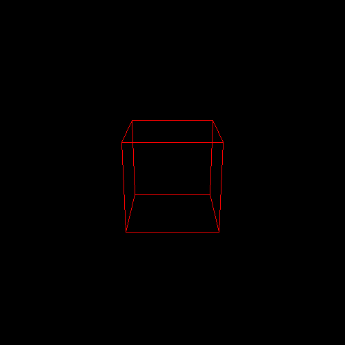
#include <vector>
#include <cmath>
#include <algorithm>
#include <iostream>
#include "model.h"
#include "geometry.h"
#include "pngimage.h"using namespace std;
const double PI = acos(-1.0);void line(Vec3i p0, Vec3i p1, PNGImage  &image, PNGColor color)
{bool steep = false;if (std::abs(p0.x - p1.x) < std::abs(p0.y - p1.y)){std::swap(p0.x, p0.y);std::swap(p1.x, p1.y);steep = true;}if (p0.x > p1.x){std::swap(p0.x, p1.x);std::swap(p0.y, p1.y);}int dx = p1.x - p0.x;int dy = std::abs(p1.y - p0.y);int y = p0.y;int d = -dx;for (int x = p0.x; x <= p1.x; x++){if (steep)image.set(y, x, color);elseimage.set(x, y, color);d = d + 2 * dy;if (d > 0){y += (p1.y > p0.y ? 1 : -1);d = d - 2 * dx;}}
}Matrix viewport(int x, int y, int w, int h, int depth) {Matrix m = Matrix::identity(4);// Please add the code here/********** Begin ********/m[0][0]=w/2;m[0][3]=x+(w/2);m[1][1]=h/2;m[1][3]=y+h/2;m[2][2]=255/2;m[2][3]=255/2;m[3][3]=1;/********** End **********/return m;
}Matrix lookat(Vec3f eye, Vec3f center, Vec3f up) {Vec3f z = (eye - center).normalize();Vec3f x = (up^z).normalize();Vec3f y = (z^x).normalize();Matrix res = Matrix::identity(4);for (int i = 0; i < 3; i++) {res[0][i] = x[i];res[1][i] = y[i];res[2][i] = z[i];res[i][3] = -center[i];}return res;
}Matrix translation(Vec3f v) {Matrix Tr = Matrix::identity(4);Tr[0][3] = v.x;Tr[1][3] = v.y;Tr[2][3] = v.z;return Tr;
}Matrix scale(float factorX, float factorY, float factorZ)
{Matrix Z = Matrix::identity(4);Z[0][0] = factorX;Z[1][1] = factorY;Z[2][2] = factorZ;return Z;
}Matrix rotation_x(float angle)
{angle = angle * PI / 180;float sinangle = sin(angle);float cosangle = cos(angle);Matrix R = Matrix::identity(4);R[1][1] = R[2][2] = cosangle;R[1][2] = -sinangle;R[2][1] = sinangle;return R;
}Matrix rotation_y(float angle)
{angle = angle * PI / 180;float sinangle = sin(angle);float cosangle = cos(angle);Matrix R = Matrix::identity(4);R[0][0] = R[2][2] = cosangle;R[0][2] = sinangle;R[2][0] = -sinangle;return R;
}Matrix rotation_z(float angle) {angle = angle * PI / 180;float sinangle = sin(angle);float cosangle = cos(angle);Matrix R = Matrix::identity(4);R[0][0] = R[1][1] = cosangle;R[0][1] = -sinangle;R[1][0] = sinangle;return R;
}int main(int argc, char** argv)
{const PNGColor white = PNGColor(255, 255, 255, 255);const PNGColor black = PNGColor(0, 0, 0, 255);const PNGColor red = PNGColor(255, 0, 0, 255);const PNGColor green = PNGColor(0, 255, 0, 255);const PNGColor blue = PNGColor(0, 0, 255, 255);const PNGColor yellow = PNGColor(255, 255, 0, 255);Model *model = NULL;Vec3f eye(0, 1.5, 4);Vec3f center(0, 0, 0);Matrix ModelView = lookat(eye, center, Vec3f(0, 1, 0));Matrix Projection = Matrix::projection(eye, center);const int width = 500;const int height = 500;const int depth = 255;// Please add the code here/********** Begin ********/Matrix ViewPort = viewport(width/4,width/4,width/2,height/2,depth);/********** End **********///generate some imagePNGImage image(width, height, PNGImage::RGBA); //Error when RGB because lodepng_get_raw_size_lct(w, h, colortype, bitdepth) > in.size() in encodeimage.init(black);model = new Model("cube.obj");for (int i = 0; i < model->nfaces(); i++){std::vector<int> face = model->face(i);for (int j = 0; j < (int)face.size(); j++){Vec3f wp0 = model->vert(face[j]);Vec3f wp1 = model->vert(face[(j + 1) % face.size()]);Matrix S0 = scale(0.5, 0.5, 0.5);Vec3f swp0 = S0 * wp0;Vec3f swp1 = S0 * wp1;Vec3f sp0 = ViewPort*Projection*ModelView*swp0;Vec3f sp1 = ViewPort*Projection*ModelView*swp1;line(sp0, sp1, image, red);}}image.flip_vertically(); // i want to have the origin at the left bottom corner of the imageimage.write_png_file("../img_step3/test.png");delete model;return 0;
}
投影变换v1.0
第1关:立方体透视投影
一.任务描述
根据提示,在右侧修改代码,并自己绘制出图形。平台会对你编写的代码进行测试。
1.本关任务
学习了解三维图形几何变换原理。 理解掌握OpenGL三维图形几何变换的方法。 理解掌握OpenGL程序的模型视图变换。 掌握OpenGL三维图形显示与观察的原理与实现。
2.预期输出
3.具体要求
(1).背景色为黑色,用 glclearcolor 来完成; (2).运用glPushMatrix()函数和glPopMatrix()函数进行矩阵操作,以中心为绘制原点,设置前景色为红色glColor3f(1.0, 0.0, 0.0),绘制单位立方体线框,用glutWireCube(1.0)完成; (3).运用glPushMatrix()函数和glPopMatrix()函数进行矩阵操作,设置前景色为黑色glColor3f(0.0, 1.0, 0.0),设置线宽为2.0用glLineWidth(2.0)完成,将原单位立方体线框沿X轴正方向平移2.0;
(4).运用glPushMatrix()函数和glPopMatrix()函数进行矩阵操作,沿X轴负方向平移2.0,设置前景色为蓝色glColor3f(0.0, 0.0, 1.0),绘制单位立方体实体用glutSolidCube(1.0)完成; (5).由图可知,中间红色为一点透视。右边绿色和左边蓝色为两点透视。通过glRotatef()旋转绿色立方体来,完成蓝色立方体的三点透视。将绿色立方体绕X轴旋转+30度。
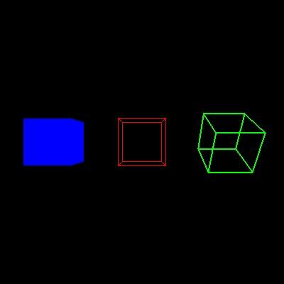
// 提示:在合适的地方修改或添加代码
#include <GL/freeglut.h>
#include<stdio.h>// 评测代码所用头文件-开始
#include<opencv2/core/core.hpp>
#include<opencv2/highgui/highgui.hpp>
#include<opencv2/imgproc/imgproc.hpp>
// 评测代码所用头文件-结束GLint winWidth = 400, winHeight =400 ; 	      //设置初始化窗口大小/*观察坐标系参数设置*/
GLfloat x0 = 0.0, yy = 0.0, z0 = 5.0;	   //设置观察坐标系原点
GLfloat xref = 0.0, yref = 0.0, zref = 0.0;	//设置观察坐标系参考点(视点)
GLfloat Vx = 0.0, Vy = 1.0, Vz = 0.0;	   //设置观察坐标系向上向量(y轴) /*观察体参数设置 */
GLfloat xwMin = -1.0, ywMin = -1.0, xwMax = 1.0, ywMax = 1.0;//设置裁剪窗口坐标范围
GLfloat dnear = 1.5, dfar = 20.0;	      //设置远、近裁剪面深度范围void init(void)
{glClearColor(0.0, 0.0, 0.0, 0.0);
}
void display(void)
{glClear(GL_COLOR_BUFFER_BIT);glLoadIdentity();/*观察变换*/gluLookAt(x0, yy, z0, xref, yref, zref, Vx, Vy, Vz);        //指定三维观察参数// 请在此添加你的代码/********** Begin ********/glPushMatrix();glColor3f(1.0, 0.0, 0.0);    //设置前景色为红色glutWireCube(1.0);   //绘制单位立方体线框glPopMatrix();glPushMatrix();glColor3f(0.0, 1.0, 0.0);    //设置前景色为黑色glLineWidth(2.0);             //设置线宽glRotatef(30,1,0,0);glTranslatef(2.0f, 0.0f, 0.0f);glutWireCube(1.0);   //绘制单位立方体线框glPopMatrix();glPushMatrix();glTranslatef(-2.0f, 0.0f, 0.0f);glColor3f(0.0, 0.0, 1.0);glutSolidCube(1.0);    //绘制单位立方体实体glPopMatrix();/********** End **********/glFlush();
}void reshape(GLint newWidth, GLint newHeight)
{/*视口变换*/glViewport(0, 0, newWidth, newHeight);	//定义视口大小/*投影变换*/glMatrixMode(GL_PROJECTION);glLoadIdentity();/*透视投影,设置透视观察体*/glFrustum(xwMin, xwMax, ywMin, ywMax, dnear, dfar);/*模型变换*/glMatrixMode(GL_MODELVIEW);winWidth = newWidth;winHeight = newHeight;
}
int main(int argc, char* argv[])
{glutInit(&argc, argv);glutInitWindowPosition(100, 100);glutInitWindowSize( 400 , 400 );        //设置初始化窗口大小glutCreateWindow("三维观察");init();glutDisplayFunc(display);glutReshapeFunc(reshape);glutMainLoopEvent();/*************以下为评测代码,与本次实验内容无关,请勿修改**************/GLubyte* pPixelData = (GLubyte*)malloc(800 * 400 * 3);//分配内存GLint viewport[4] = { 0 };glReadBuffer(GL_FRONT);glPixelStorei(GL_UNPACK_ALIGNMENT, 4);glGetIntegerv(GL_VIEWPORT, viewport);glReadPixels(viewport[0], viewport[1], viewport[2], viewport[3], GL_RGB, GL_UNSIGNED_BYTE, pPixelData);cv::Mat img;std::vector<cv::Mat> imgPlanes;img.create(400, 400, CV_8UC3);cv::split(img, imgPlanes);for (int i = 0; i < 400; i++) {unsigned char* plane0Ptr = imgPlanes[0].ptr<unsigned char>(i);unsigned char* plane1Ptr = imgPlanes[1].ptr<unsigned char>(i);unsigned char* plane2Ptr = imgPlanes[2].ptr<unsigned char>(i);for (int j = 0; j < 400; j++) {int k = 3 * (i * 400 + j);plane2Ptr[j] = pPixelData[k];plane1Ptr[j] = pPixelData[k + 1];plane0Ptr[j] = pPixelData[k + 2];}}cv::merge(imgPlanes, img);cv::flip(img, img, 0);cv::namedWindow("openglGrab");cv::imshow("openglGrab", img);//cv::waitKey();cv::imwrite("../img_step4/test.jpg", img);return 0;
}
第2关:立方体平行投影
一.任务描述
根据提示,在右侧修改代码,并自己绘制出图形。平台会对你编写的代码进行测试。
1.本关任务
学习了解三维图形几何变换原理。 理解掌握OpenGL三维图形几何变换的方法。 理解掌握OpenGL程序的模型视图变换。 掌握OpenGL三维图形显示与观察的原理与实现。
2.预期输出
3.具体要求
(1).背景色为黑色,用 glclearcolor 来完成;
(2).运用glPushMatrix()函数和glPopMatrix()函数进行矩阵操作,以中心为绘制原点,设置前景色为红色glColor3f(1.0, 0.0, 0.0),绘制单位立方体线框,用glutWireCube(1.0)完成;
(3).运用glPushMatrix()函数和glPopMatrix()函数进行矩阵操作,设置前景色为黑色glColor3f(0.0, 1.0, 0.0),设置线宽为2.0用glLineWidth(2.0)完成,将原单位立方体线框沿X轴正方向平移2.0;
(4).运用glPushMatrix()函数和glPopMatrix()函数进行矩阵操作,沿X轴负方向平移2.0,设置前景色为蓝色glColor3f(0.0, 0.0, 1.0),绘制单位立方体实体用glutSolidCube(1.0)完成;(5).进行平行投影调用glOrtho()函数,坐标为(左,右,下,上,近,远),坐标为glOrtho(-3.0, 3.0, -3.0, 3.0,-100.0, 100.0);

// 提示:在合适的地方修改或添加代码
#include <GL/freeglut.h>
#include<stdio.h>// 评测代码所用头文件-开始
#include<opencv2/core/core.hpp>
#include<opencv2/highgui/highgui.hpp>
#include<opencv2/imgproc/imgproc.hpp>
// 评测代码所用头文件-结束GLint winWidth = 400, winHeight =400 ; 	      //设置初始化窗口大小/*观察坐标系参数设置*/
GLfloat x0 = 0.0, yy = 0.0, z0 = 5.0;	   //设置观察坐标系原点
GLfloat xref = 0.0, yref = 0.0, zref = 0.0;	//设置观察坐标系参考点(视点)
GLfloat Vx = 0.0, Vy = 1.0, Vz = 0.0;	   //设置观察坐标系向上向量(y轴) /*观察体参数设置 */
GLfloat xwMin = -1.0, ywMin = -1.0, xwMax = 1.0, ywMax = 1.0;//设置裁剪窗口坐标范围
GLfloat dnear = 1.5, dfar = 20.0;	      //设置远、近裁剪面深度范围void init(void)
{glClearColor(0.0, 0.0, 0.0, 0.0);
}
void display(void)
{glClear(GL_COLOR_BUFFER_BIT);glLoadIdentity();/*观察变换*/gluLookAt(x0, yy, z0, xref, yref, zref, Vx, Vy, Vz);        //指定三维观察参数// 请在此添加你的代码/********** Begin ********/glPushMatrix();glColor3f(1.0, 0.0, 0.0);    //设置前景色为红色glutWireCube(1.0);   //绘制单位立方体线框glPopMatrix();glPushMatrix();glColor3f(0.0, 1.0, 0.0);    //设置前景色为黑色glLineWidth(2.0);             //设置线宽glTranslatef(2.0f, 0.0f, 0.0f);glutWireCube(1.0);   //绘制单位立方体线框glPopMatrix();glPushMatrix();glTranslatef(-2.0f, 0.0f, 0.0f);glColor3f(0.0, 0.0, 1.0);glutSolidCube(1.0);    //绘制单位立方体实体glPopMatrix();/********** End **********/glFlush();
}void reshape(GLint newWidth, GLint newHeight)
{/*视口变换*/glViewport(0, 0, newWidth, newHeight);	//定义视口大小/*投影变换*/glMatrixMode(GL_PROJECTION);glLoadIdentity();/*平行投影*/glOrtho( -3,3 ,-3 ,3 ,-100 ,100 );/*模型变换*/glMatrixMode(GL_MODELVIEW);winWidth = newWidth;winHeight = newHeight;
}
int main(int argc, char* argv[])
{glutInit(&argc, argv);glutInitWindowPosition(100, 100);glutInitWindowSize( 400 , 400 );        //设置初始化窗口大小glutCreateWindow("三维观察");init();glutDisplayFunc(display);glutReshapeFunc(reshape);glutMainLoopEvent();/*************以下为评测代码,与本次实验内容无关,请勿修改**************/GLubyte* pPixelData = (GLubyte*)malloc(800 * 400 * 3);//分配内存GLint viewport[4] = { 0 };glReadBuffer(GL_FRONT);glPixelStorei(GL_UNPACK_ALIGNMENT, 4);glGetIntegerv(GL_VIEWPORT, viewport);glReadPixels(viewport[0], viewport[1], viewport[2], viewport[3], GL_RGB, GL_UNSIGNED_BYTE, pPixelData);cv::Mat img;std::vector<cv::Mat> imgPlanes;img.create(400, 400, CV_8UC3);cv::split(img, imgPlanes);for (int i = 0; i < 400; i++) {unsigned char* plane0Ptr = imgPlanes[0].ptr<unsigned char>(i);unsigned char* plane1Ptr = imgPlanes[1].ptr<unsigned char>(i);unsigned char* plane2Ptr = imgPlanes[2].ptr<unsigned char>(i);for (int j = 0; j < 400; j++) {int k = 3 * (i * 400 + j);plane2Ptr[j] = pPixelData[k];plane1Ptr[j] = pPixelData[k + 1];plane0Ptr[j] = pPixelData[k + 2];}}cv::merge(imgPlanes, img);cv::flip(img, img, 0);cv::namedWindow("openglGrab");cv::imshow("openglGrab", img);//cv::waitKey();cv::imwrite("../img_step3/test.jpg", img);return 0;
}
投影变换v2.0
第1关:一点透视
一. 任务描述
1. 本关任务
(1) 理解透视投影变换的方法; (2) 将projection函数和main函数中的空白部分补充完整。
2. 输入
(1) 代码将自动输入一个边长为1的obj正方体模型,具体模型如下图:
(2) 代码自动将模型投影到二维平面中心生成一个边长为1的立方体,经过模型变换和投影变换后生成三个绿色的方体,三个立方体的投影变换eye的坐标均为(0,0,5),具体图片如下所示:
(3) 参考已有代码,将中心立绿色方体的顶点分别向y轴负方向平移1.2个单位,绘制一个红色立方体。再将红色立方体顶点分别向x轴正,负两个方向平移1.2个单位,绘制两个红色立方体。三个立方体的投影变换eye的坐标均为(0,0,4); (4) 将中心绿色立方体的顶点分别向y轴正方向平移1.2个单位,绘制一个黄色立方体。再将黄色立方体顶点分别向x轴正,负两个方向平移1.2个单位,绘制两个黄色立方体。三个立方体的投影变换eye的坐标均为(0,0,8);
3. 输出
具体结果如下图所示:

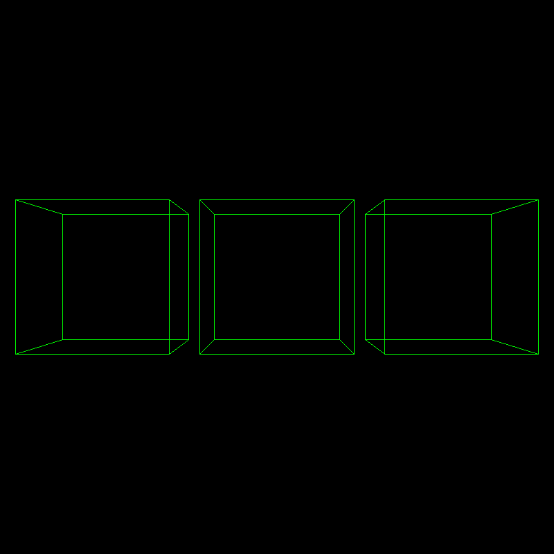
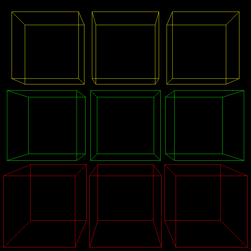
#include <vector>
#include <cmath>
#include <algorithm>
#include <iostream>
#include "model.h"
#include "geometry.h"
#include "pngimage.h"
using namespace std;
const double PI = acos(-1.0);
void line(Vec3i p0, Vec3i p1, PNGImage  &image, PNGColor color)
{bool steep = false;if (std::abs(p0.x - p1.x) < std::abs(p0.y - p1.y)){std::swap(p0.x, p0.y);std::swap(p1.x, p1.y);steep = true;}if (p0.x > p1.x){std::swap(p0.x, p1.x);std::swap(p0.y, p1.y);}int dx = p1.x - p0.x;int dy = std::abs(p1.y - p0.y);int y = p0.y;int d = -dx;for (int x = p0.x; x <= p1.x; x++){if (steep)image.set(y, x, color);elseimage.set(x, y, color);d = d + 2 * dy;if (d > 0){y += (p1.y > p0.y ? 1 : -1);d = d - 2 * dx;}}
}
Matrix projection(Vec3f eye, Vec3f center)
{Matrix m = Matrix::identity(4);// Please add the code here/********** Begin ********/m[3][2] = -1.f / (eye - center).norm();/********** End **********/return m;
}
Matrix viewport(int x, int y, int w, int h, int depth) {Matrix m = Matrix::identity(4);m[0][3] = x + w / 2.f;m[1][3] = y + h / 2.f;m[2][3] = depth / 2.f;m[0][0] = w / 2.f;m[1][1] = h / 2.f;m[2][2] = depth / 2.f;return m;
}
Matrix lookat(Vec3f eye, Vec3f center, Vec3f up) {Vec3f z = (eye - center).normalize();Vec3f x = (up^z).normalize();Vec3f y = (z^x).normalize();Matrix res = Matrix::identity(4);for (int i = 0; i < 3; i++) {res[0][i] = x[i];res[1][i] = y[i];res[2][i] = z[i];res[i][3] = -center[i];}return res;
}
Matrix translation(Vec3f v) {Matrix Tr = Matrix::identity(4);Tr[0][3] = v.x;Tr[1][3] = v.y;Tr[2][3] = v.z;return Tr;
}
Matrix scale(float factorX, float factorY, float factorZ)
{Matrix Z = Matrix::identity(4);Z[0][0] = factorX;Z[1][1] = factorY;Z[2][2] = factorZ;return Z;
}
Matrix rotation_x(float angle)
{angle = angle * PI / 180;float sinangle = sin(angle);float cosangle = cos(angle);Matrix R = Matrix::identity(4);R[1][1] = R[2][2] = cosangle;R[1][2] = -sinangle;R[2][1] = sinangle;return R;
}
Matrix rotation_y(float angle)
{angle = angle * PI / 180;float sinangle = sin(angle);float cosangle = cos(angle);Matrix R = Matrix::identity(4);R[0][0] = R[2][2] = cosangle;R[0][2] = sinangle;R[2][0] = -sinangle;return R;
}
Matrix rotation_z(float angle) {angle = angle * PI / 180;float sinangle = sin(angle);float cosangle = cos(angle);Matrix R = Matrix::identity(4);R[0][0] = R[1][1] = cosangle;R[0][1] = -sinangle;R[1][0] = sinangle;return R;
}
int main(int argc, char** argv)
{const PNGColor white = PNGColor(255, 255, 255, 255);const PNGColor black = PNGColor(0, 0, 0, 255);const PNGColor red = PNGColor(255, 0, 0, 255);const PNGColor green = PNGColor(0, 255, 0, 255);const PNGColor blue = PNGColor(0, 0, 255, 255);const PNGColor yellow = PNGColor(255, 255, 0, 255);Model *model = NULL;const int width = 800;const int height = 800;const int depth = 255;Vec3f center(0, 0, 0);Matrix ViewPort = viewport(width / 4, width / 4, width / 2, height / 2, depth);//generate some imagePNGImage image(width, height, PNGImage::RGBA); image.init(black);model = new Model("cube.obj");for (int i = 0; i < model->nfaces(); i++){std::vector<int> face = model->face(i);for (int j = 0; j < (int)face.size(); j++){Vec3f wp0 = model->vert(face[j]);Vec3f wp1 = model->vert(face[(j + 1) % face.size()]);Matrix S0 = scale(0.5, 0.5, 0.5);Vec3f swp0 = S0 * wp0;Vec3f swp1 = S0 * wp1;// 一点透视 float t[3] = { -1.2, 0, 1.2 };Matrix ModelView = Matrix::identity(4);PNGColor clr[3] = { red, green, yellow };Vec3f eye2(0, 0, 5);Matrix Projection2 = projection(eye2, center);for (int j = 0; j < 3; j++){ModelView = translation(Vec3f(t[j], t[1], 0));Vec3f op0 = ViewPort * Projection2 * ModelView * swp0;Vec3f op1 = ViewPort * Projection2 * ModelView *swp1;line(op0, op1, image, green);}// Please add the code here/********** Begin ********/Vec3f eye1(0, 0, 4);Matrix Projection1 = projection(eye1, center);for (int j = 0; j < 3; j++){ModelView = translation(Vec3f(t[j], t[0], 0));Vec3f op0 = ViewPort * Projection1 * ModelView * swp0;Vec3f op1 = ViewPort * Projection1 * ModelView *swp1;line(op0, op1, image, red);}Vec3f eye3(0, 0, 8);Matrix Projection3 = projection(eye3, center);for (int j = 0; j < 3; j++){ModelView = translation(Vec3f(t[j], t[2], 0));Vec3f op0 = ViewPort * Projection3 * ModelView * swp0;Vec3f op1 = ViewPort * Projection3 * ModelView *swp1;line(op0, op1, image, yellow);}/********** End **********/}}image.flip_vertically(); // i want to have the origin at the left bottom corner of the imageimage.write_png_file("../img_step1/test.png");delete model;return 0;
}
第2关:两点透视
一. 任务描述
1. 本关任务
(1) 理解透视投影变换的方法; (2) 将main函数中的空白部分补充完整。
2. 输入
(1) 代码将自动输入一个边长为1的obj正方体模型,具体模型如下图:
(2) 代码自动将模型投影到二维平面中心生成一个边长为1的绿色立方体; (3) 改变模型位置,产生两点透视: 将绿色立方体顶点分别沿z轴逆时针旋转45度,向y轴正方向平移1.2个单位,绘制一个红色立方体。再将红色立方体顶点分别向x轴正,负两个方向平移1.2个单位,绘制两个红色立方体。最后对三个红立方体进行投影变换,变换矩阵Projection已给出; (4) 改变视点与模型位置,产生两点透视(先模型变换再观察变换): 首先将立绿色方体的顶点分别向x轴正,负两个方向平移1.2个单位,绘制两个绿色立方体。然后对三个绿色立方体分别进行观察变换,将参数eye沿y轴顺时针旋转45度作为相机坐标,中心点坐标为center,向上矢量为Vec3f(0, 1, 0)。最后对三个绿立方体进行投影变换,变换矩阵Projection已给出; (5) 改变视点与模型位置,产生两点透视(先观察变换再模型变换): 首先对绿色立方体分别进行观察变换,将参数eye沿y轴顺时针旋转45度作为相机坐标,中心点坐标为center,向上矢量为Vec3f(0, 1, 0)。将绿色立方体向y轴负方向平移1.2个单位,绘制一个黄色立方体。再将黄色立方体顶点分别向x轴正,负两个方向平移1.2个单位,绘制两个黄色立方体。最后对三个黄立方体进行投影变换,变换矩阵Projection已给出。
3. 输出
具体结果如下图所示:
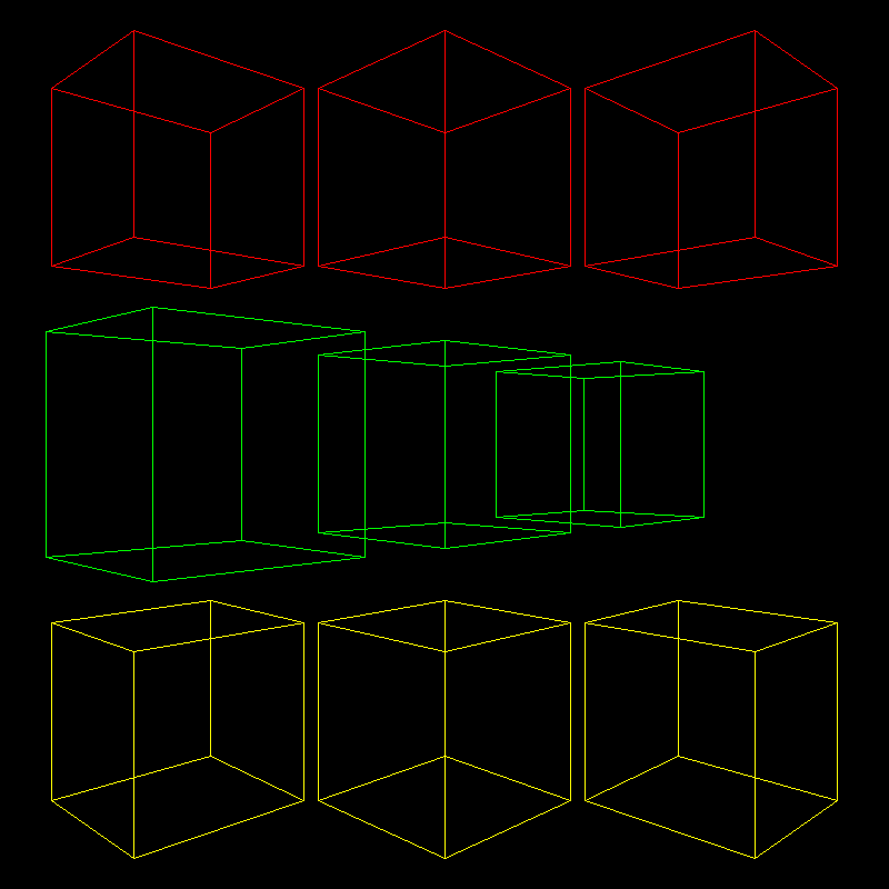
#include <vector>
#include <cmath>
#include <algorithm>
#include <iostream>
#include "model.h"
#include "geometry.h"
#include "pngimage.h"using namespace std;
const double PI = acos(-1.0);void line(Vec3i p0, Vec3i p1, PNGImage  &image, PNGColor color)
{bool steep = false;if (std::abs(p0.x - p1.x) < std::abs(p0.y - p1.y)){std::swap(p0.x, p0.y);std::swap(p1.x, p1.y);steep = true;}if (p0.x > p1.x){std::swap(p0.x, p1.x);std::swap(p0.y, p1.y);}int dx = p1.x - p0.x;int dy = std::abs(p1.y - p0.y);int y = p0.y;int d = -dx;for (int x = p0.x; x <= p1.x; x++){if (steep)image.set(y, x, color);elseimage.set(x, y, color);d = d + 2 * dy;if (d > 0){y += (p1.y > p0.y ? 1 : -1);d = d - 2 * dx;}}
}Matrix projection(Vec3f eye, Vec3f center)
{Matrix m = Matrix::identity(4);m[3][2] = -1.f / (eye - center).norm();return m;
}Matrix viewport(int x, int y, int w, int h, int depth) {Matrix m = Matrix::identity(4);m[0][3] = x + w / 2.f;m[1][3] = y + h / 2.f;m[2][3] = depth / 2.f;m[0][0] = w / 2.f;m[1][1] = h / 2.f;m[2][2] = depth / 2.f;return m;
}Matrix lookat(Vec3f eye, Vec3f center, Vec3f up) {Vec3f z = (eye - center).normalize();Vec3f x = (up^z).normalize();Vec3f y = (z^x).normalize();Matrix res = Matrix::identity(4);for (int i = 0; i < 3; i++) {res[0][i] = x[i];res[1][i] = y[i];res[2][i] = z[i];res[i][3] = -center[i];}return res;
}Matrix translation(Vec3f v) {Matrix Tr = Matrix::identity(4);Tr[0][3] = v.x;Tr[1][3] = v.y;Tr[2][3] = v.z;return Tr;
}Matrix scale(float factorX, float factorY, float factorZ)
{Matrix Z = Matrix::identity(4);Z[0][0] = factorX;Z[1][1] = factorY;Z[2][2] = factorZ;return Z;
}Matrix rotation_x(float angle)
{angle = angle * PI / 180;float sinangle = sin(angle);float cosangle = cos(angle);Matrix R = Matrix::identity(4);R[1][1] = R[2][2] = cosangle;R[1][2] = -sinangle;R[2][1] = sinangle;return R;
}Matrix rotation_y(float angle)
{angle = angle * PI / 180;float sinangle = sin(angle);float cosangle = cos(angle);Matrix R = Matrix::identity(4);R[0][0] = R[2][2] = cosangle;R[0][2] = sinangle;R[2][0] = -sinangle;return R;
}Matrix rotation_z(float angle) {angle = angle * PI / 180;float sinangle = sin(angle);float cosangle = cos(angle);Matrix R = Matrix::identity(4);R[0][0] = R[1][1] = cosangle;R[0][1] = -sinangle;R[1][0] = sinangle;return R;
}int main(int argc, char** argv)
{const PNGColor white = PNGColor(255, 255, 255, 255);const PNGColor black = PNGColor(0, 0, 0, 255);const PNGColor red = PNGColor(255, 0, 0, 255);const PNGColor green = PNGColor(0, 255, 0, 255);const PNGColor blue = PNGColor(0, 0, 255, 255);const PNGColor yellow = PNGColor(255, 255, 0, 255);Model *model = NULL;const int width = 800;const int height = 800;const int depth = 255;//generate some imagePNGImage image(width, height, PNGImage::RGBA); //Error when RGB because lodepng_get_raw_size_lct(w, h, colortype, bitdepth) > in.size() in encodeimage.init(black);model = new Model("cube.obj");Vec3f eye(0, 0, 4);Vec3f center(0, 0, 0);Matrix ModelView = Matrix::identity(4);Matrix Projection = projection(eye, center);Matrix ViewPort = viewport(width / 4, width / 4, width / 2, height / 2, depth);for (int i = 0; i < model->nfaces(); i++){std::vector<int> face = model->face(i);for (int j = 0; j < (int)face.size(); j++){Vec3f wp0 = model->vert(face[j]);Vec3f wp1 = model->vert(face[(j + 1) % face.size()]);Matrix S0 = scale(0.4, 0.4, 0.4);Vec3f swp0 = S0 * wp0;Vec3f swp1 = S0 * wp1;// Please add the code here/********** Begin ********/float tx[3] = { -1.2, 0, 1.2 };for (int i = 0; i < 3; i++){ModelView = translation(Vec3f(tx[i], 1.2, 0)) * rotation_y(45);Vec3f op0 = ViewPort * Projection * ModelView * swp0;Vec3f op1 = ViewPort * Projection * ModelView * swp1;line(op0, op1, image, red);}// 改变视点与模型位置,产生两点透视 // 先模型变换,再视点变换Vec3f eye1 = rotation_y(-45) * eye;for (int j = 0; j < 3; j++){Matrix ModelView1 = lookat(eye1, center, Vec3f(0, 1, 0)) * translation(Vec3f(tx[j], 0, 0));Vec3f vp0 = ViewPort * Projection * ModelView1 * swp0;Vec3f vp1 = ViewPort * Projection * ModelView1 *swp1;line(vp0, vp1, image, green);}// 改变视点与模型位置,产生两点透视 // 先视点变换,再模型变换for (int k = 0; k < 3; k++){    Matrix ModelView1 = translation(Vec3f(tx[k], -1.2, 0)) * lookat(eye1, center, Vec3f(0, 1, 0));Vec3f vp0 = ViewPort * Projection * ModelView1 * swp0;Vec3f vp1 = ViewPort * Projection * ModelView1 *swp1;line(vp0, vp1, image, yellow);}    /********** End ********/}}image.flip_vertically(); // i want to have the origin at the left bottom corner of the imageimage.write_png_file("../img_step2/test.png");delete model;return 0;
}
第3关:三视图与正等测投影
一. 任务描述
1. 本关任务
(1) 理解投影变换的方法; (2) 将main函数中的空白部分补充完整。
2. 输入
(1) 代码将自动输入一个边长为1的obj正方体模型,具体模型如下图:
(2) 代码自动将模型投影到二维平面,经过模型变换,生成一个长宽高不等的立方体; (3) 将立方体沿Z轴向XOY平面正投影,并绘制出一个白色矩形; (4) 将立方体沿Y轴向XOZ平面正投影,然后沿X轴逆时针旋转90度,最后沿着Y轴负方向平移1.2个单位长度,绘制一个红色矩形; (5) 将立方体沿X轴向YOZ平面正投影,然后沿Y轴顺时针旋转90度,最后沿着X轴负方向平移1.2个单位长度,绘制一个绿色矩形; (6) 绘制正等测投影图,将立方体沿Z轴逆时针旋转45度,再沿X轴逆时针旋转35.25度,然后沿Z轴向XOY平面正投影。最后沿着Y轴正方向平移1.2个单位长度,绘制一个黄色立方体;
3. 输出
具体结果如下图所示:
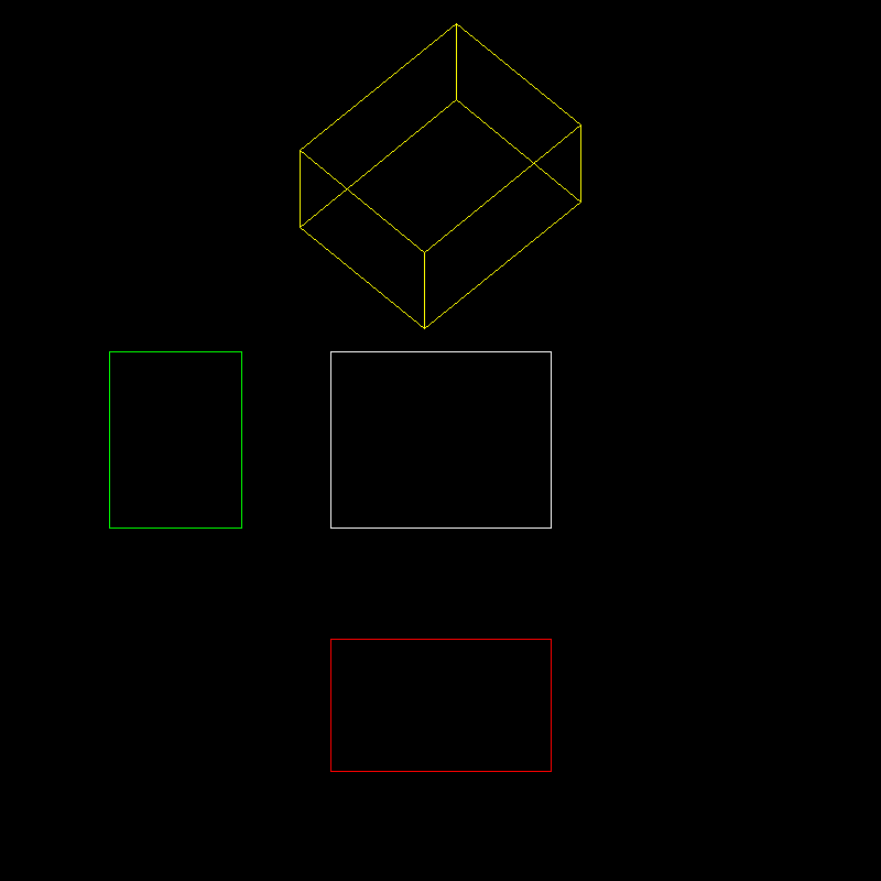
#include <vector>
#include <cmath>
#include <algorithm>
#include <iostream>
#include "model.h"
#include "geometry.h"
#include "pngimage.h"using namespace std;
const double PI = acos(-1.0);void line(Vec3i p0, Vec3i p1, PNGImage  &image, PNGColor color)
{bool steep = false;if (std::abs(p0.x - p1.x) < std::abs(p0.y - p1.y)){std::swap(p0.x, p0.y);std::swap(p1.x, p1.y);steep = true;}if (p0.x > p1.x){std::swap(p0.x, p1.x);std::swap(p0.y, p1.y);}int dx = p1.x - p0.x;int dy = std::abs(p1.y - p0.y);int y = p0.y;int d = -dx;for (int x = p0.x; x <= p1.x; x++){if (steep)image.set(y, x, color);elseimage.set(x, y, color);d = d + 2 * dy;if (d > 0){y += (p1.y > p0.y ? 1 : -1);d = d - 2 * dx;}}
}Matrix projection(Vec3f eye, Vec3f center)
{Matrix m = Matrix::identity(4);m[3][2] = -1.f / (eye - center).norm();return m;
}Matrix viewport(int x, int y, int w, int h, int depth) {Matrix m = Matrix::identity(4);m[0][3] = x + w / 2.f;m[1][3] = y + h / 2.f;m[2][3] = depth / 2.f;m[0][0] = w / 2.f;m[1][1] = h / 2.f;m[2][2] = depth / 2.f;return m;
}Matrix lookat(Vec3f eye, Vec3f center, Vec3f up) {Vec3f z = (eye - center).normalize();Vec3f x = (up^z).normalize();Vec3f y = (z^x).normalize();Matrix res = Matrix::identity(4);for (int i = 0; i < 3; i++) {res[0][i] = x[i];res[1][i] = y[i];res[2][i] = z[i];res[i][3] = -center[i];}return res;
}Matrix translation(Vec3f v) {Matrix Tr = Matrix::identity(4);Tr[0][3] = v.x;Tr[1][3] = v.y;Tr[2][3] = v.z;return Tr;
}Matrix scale(float factorX, float factorY, float factorZ)
{Matrix Z = Matrix::identity(4);Z[0][0] = factorX;Z[1][1] = factorY;Z[2][2] = factorZ;return Z;
}Matrix rotation_x(float angle)
{angle = angle * PI / 180;float sinangle = sin(angle);float cosangle = cos(angle);Matrix R = Matrix::identity(4);R[1][1] = R[2][2] = cosangle;R[1][2] = -sinangle;R[2][1] = sinangle;return R;
}Matrix rotation_y(float angle)
{angle = angle * PI / 180;float sinangle = sin(angle);float cosangle = cos(angle);Matrix R = Matrix::identity(4);R[0][0] = R[2][2] = cosangle;R[0][2] = sinangle;R[2][0] = -sinangle;return R;
}Matrix rotation_z(float angle) {angle = angle * PI / 180;float sinangle = sin(angle);float cosangle = cos(angle);Matrix R = Matrix::identity(4);R[0][0] = R[1][1] = cosangle;R[0][1] = -sinangle;R[1][0] = sinangle;return R;
}int main(int argc, char** argv)
{const PNGColor white = PNGColor(255, 255, 255, 255);const PNGColor black = PNGColor(0, 0, 0, 255);const PNGColor red = PNGColor(255, 0, 0, 255);const PNGColor green = PNGColor(0, 255, 0, 255);const PNGColor blue = PNGColor(0, 0, 255, 255);const PNGColor yellow = PNGColor(255, 255, 0, 255);Model *model = NULL;const int width = 800;const int height = 800;const int depth = 255;//generate some imagePNGImage image(width, height, PNGImage::RGBA); //Error when RGB because lodepng_get_raw_size_lct(w, h, colortype, bitdepth) > in.size() in encodeimage.init(black);model = new Model("cube.obj");Matrix ViewPort = viewport(width / 4, width / 4, width / 2, height / 2, depth);for (int i = 0; i < model->nfaces(); i++){std::vector<int> face = model->face(i);for (int j = 0; j < (int)face.size(); j++){Vec3f wp0 = model->vert(face[j]);Vec3f wp1 = model->vert(face[(j + 1) % face.size()]);Matrix S0 = scale(0.5, 0.4, 0.3);Vec3f swp0 = S0 * wp0;Vec3f swp1 = S0 * wp1;/********** Begin ********/Matrix ProjectionX = Matrix::identity(4);ProjectionX[0][0] = 0.0f;Matrix ProjectionY = Matrix::identity(4);ProjectionY[1][1] = 0.0f;Matrix ProjectionZ = Matrix::identity(4);ProjectionZ[2][2] = 0.0f;//沿Z轴向XOY平面投影 Vec3f zp0 = ViewPort * ProjectionZ * swp0;Vec3f zp1 = ViewPort * ProjectionZ * swp1;line(zp0, zp1, image, white);//沿Y轴向XOZ平面投影,再旋转与平移Matrix rx = rotation_x(90);Matrix ty = translation(Vec3f(0, -1.2f, 0));Vec3f yp0 = ViewPort * ty * rx * ProjectionY * swp0;Vec3f yp1 = ViewPort * ty * rx * ProjectionY * swp1;line(yp0, yp1, image, red);//沿X轴向YOZ平面投影,再旋转与平移Matrix ry = rotation_y(-90);Matrix tx = translation(Vec3f(-1.2f, 0, 0));Vec3f xp0 = ViewPort * tx * ry * ProjectionX * swp0;Vec3f xp1 = ViewPort * tx * ry * ProjectionX * swp1;line(xp0, xp1, image, green);//正等测投影图Matrix rz = rotation_z(45);Matrix rx1 = rotation_x(35.25);Matrix ty1 = translation(Vec3f(0, 1.2f, 0));Vec3f rp0 = ViewPort * ty1 * ProjectionZ * rx1 * rz *swp0;Vec3f rp1 = ViewPort * ty1 * ProjectionZ * rx1 * rz *swp1;line(rp0, rp1, image, yellow);/********** end ********/}}image.flip_vertically(); // i want to have the origin at the left bottom corner of the imageimage.write_png_file("../img_step3/test.png");delete model;return 0;
}
第4关:视口变换与三视图
一. 任务描述
1. 本关任务
(1) 理解投影变换的方法; (2) 将main函数中的空白部分补充完整。
2. 输入
(1) 代码将自动输入一个边长为1的obj正方体模型,具体模型如下图:
(2) 代码自动将模型投影到二维平面,经过模型变换,生成一个长宽高不等的立方体,并将显示窗口一分为四,分为四个视口,每个视口大小均为原窗口大小的一半。红绿两线为四个视口的分隔线; (3) 在第一视口ViewPort中,首先将立方体沿Z轴向XOY平面投影。然后进行视口变换ViewPort,并绘制出一个白色矩形; (4) 在第二视口ViewPort1中,首先将立方体沿X轴向YOZ平面投影。然后沿Y轴顺时针旋转90度,最后进行视口变换ViewPort1,绘制一个绿色矩形; (5) 在第三视口ViewPort2中,首先将立方体沿Y轴向XOZ平面投影。然后沿X轴逆时针旋转90度,最后进行视口变换ViewPort2,绘制一个红矩形; (6) 在第四视口ViewPort3中,首先将立方体沿Y轴顺时针旋转45度,然后进行投影变换,投影变换参数eye和center已给出。最后进行视口变换ViewPort3,绘制一个黄色立方体。
3. 输出
具体结果如下图所示:
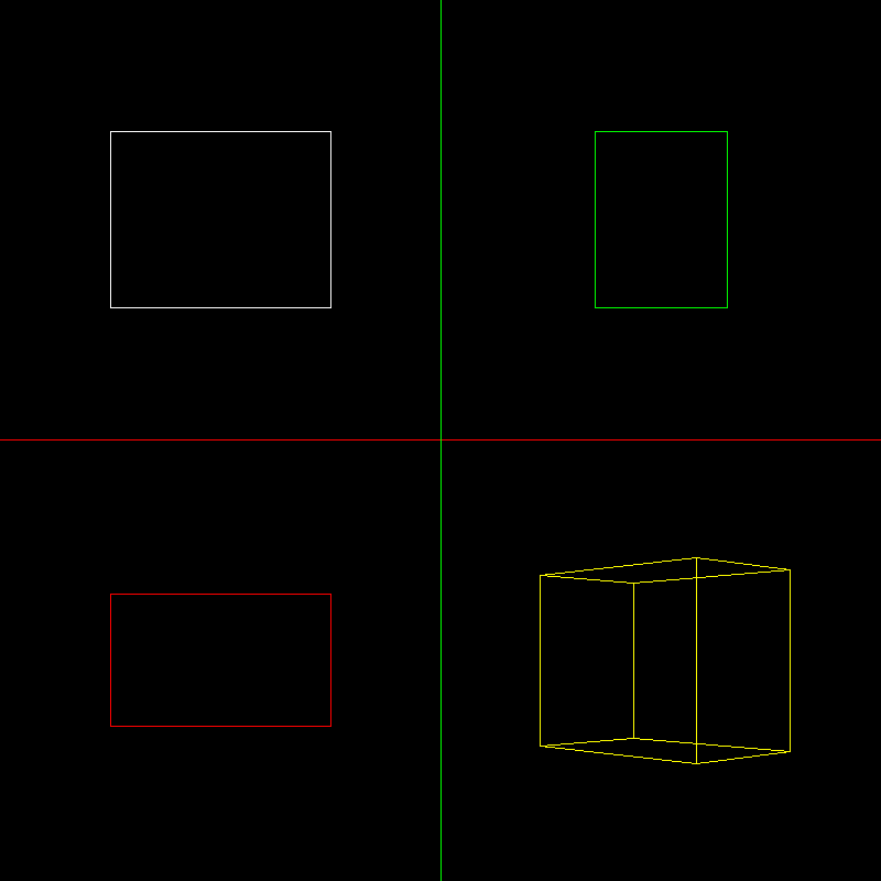
#include <vector>
#include <cmath>
#include <algorithm>
#include <iostream>
#include "model.h"
#include "geometry.h"
#include "pngimage.h"
using namespace std;
const double PI = acos(-1.0);
void line(Vec3i p0, Vec3i p1, PNGImage  &image, PNGColor color)
{bool steep = false;if (std::abs(p0.x - p1.x) < std::abs(p0.y - p1.y)){std::swap(p0.x, p0.y);std::swap(p1.x, p1.y);steep = true;}if (p0.x > p1.x){std::swap(p0.x, p1.x);std::swap(p0.y, p1.y);}int dx = p1.x - p0.x;int dy = std::abs(p1.y - p0.y);int y = p0.y;int d = -dx;for (int x = p0.x; x <= p1.x; x++){if (steep)image.set(y, x, color);elseimage.set(x, y, color);d = d + 2 * dy;if (d > 0){y += (p1.y > p0.y ? 1 : -1);d = d - 2 * dx;}}
}
Matrix projection(Vec3f eye, Vec3f center)
{Matrix m = Matrix::identity(4);m[3][2] = -1.f / (eye - center).norm();return m;
}
Matrix viewport(int x, int y, int w, int h, int depth) {Matrix m = Matrix::identity(4);m[0][3] = x + w / 2.f;m[1][3] = y + h / 2.f;m[2][3] = depth / 2.f;m[0][0] = w / 2.f;m[1][1] = h / 2.f;m[2][2] = depth / 2.f;return m;
}
Matrix lookat(Vec3f eye, Vec3f center, Vec3f up) {Vec3f z = (eye - center).normalize();Vec3f x = (up^z).normalize();Vec3f y = (z^x).normalize();Matrix res = Matrix::identity(4);for (int i = 0; i < 3; i++) {res[0][i] = x[i];res[1][i] = y[i];res[2][i] = z[i];res[i][3] = -center[i];}return res;
}
Matrix translation(Vec3f v) {Matrix Tr = Matrix::identity(4);Tr[0][3] = v.x;Tr[1][3] = v.y;Tr[2][3] = v.z;return Tr;
}
Matrix scale(float factorX, float factorY, float factorZ)
{Matrix Z = Matrix::identity(4);Z[0][0] = factorX;Z[1][1] = factorY;Z[2][2] = factorZ;return Z;
}
Matrix rotation_x(float angle)
{angle = angle * PI / 180;float sinangle = sin(angle);float cosangle = cos(angle);Matrix R = Matrix::identity(4);R[1][1] = R[2][2] = cosangle;R[1][2] = -sinangle;R[2][1] = sinangle;return R;
}
Matrix rotation_y(float angle)
{angle = angle * PI / 180;float sinangle = sin(angle);float cosangle = cos(angle);Matrix R = Matrix::identity(4);R[0][0] = R[2][2] = cosangle;R[0][2] = sinangle;R[2][0] = -sinangle;return R;
}
Matrix rotation_z(float angle) {angle = angle * PI / 180;float sinangle = sin(angle);float cosangle = cos(angle);Matrix R = Matrix::identity(4);R[0][0] = R[1][1] = cosangle;R[0][1] = -sinangle;R[1][0] = sinangle;return R;
}
int main(int argc, char** argv)
{const PNGColor white = PNGColor(255, 255, 255, 255);const PNGColor black = PNGColor(0, 0, 0, 255);const PNGColor red = PNGColor(255, 0, 0, 255);const PNGColor green = PNGColor(0, 255, 0, 255);const PNGColor blue = PNGColor(0, 0, 255, 255);const PNGColor yellow = PNGColor(255, 255, 0, 255);Model *model = NULL;const int width = 800;const int height = 800;const int depth = 255;//generate some imagePNGImage image(width, height, PNGImage::RGBA); //Error when RGB because lodepng_get_raw_size_lct(w, h, colortype, bitdepth) > in.size() in encodeimage.init(black);model = new Model("cube.obj");Vec3f eye(0, 0, 4);Vec3f center(0, 0, 0);Matrix ProjectionX = Matrix::identity(4);ProjectionX[0][0] = 0.0f;Matrix ProjectionY = Matrix::identity(4);ProjectionY[1][1] = 0.0f;Matrix ProjectionZ = Matrix::identity(4);ProjectionZ[2][2] = 0.0f;Matrix ViewPort = viewport(0, height / 2, width / 2, height / 2, depth);Matrix ViewPort1 = viewport(width / 2, height / 2, width / 2, height / 2, depth);Matrix ViewPort2 = viewport(0, 0, width / 2, height / 2, depth);Matrix ViewPort3 = viewport(width / 2, 0, width / 2, height / 2, depth);// 绘制视口分隔线Vec3f x1(0.f, height / 2, 0.f), x2(width, height / 2, 0.f);Vec3f y1(width / 2, 0.f, 0.f), y2(width / 2, height, 0.f);line(x1, x2, image, red);line(y1, y2, image, green);for (int i = 0; i < model->nfaces(); i++){std::vector<int> face = model->face(i);for (int j = 0; j < (int)face.size(); j++){Vec3f wp0 = model->vert(face[j]);Vec3f wp1 = model->vert(face[(j + 1) % face.size()]);Matrix S0 = scale(0.5, 0.4, 0.3);Vec3f swp0 = S0 * wp0;Vec3f swp1 = S0 * wp1;// Please add the code here/********** Begin ********///沿Z轴向XOY平面投影 Vec3f zp0 = ViewPort * ProjectionZ * swp0;Vec3f zp1 = ViewPort * ProjectionZ * swp1;line(zp0, zp1, image, white);//沿X轴向YOZ平面投影,再旋转与平移Matrix ry = rotation_y(-90);Vec3f xp0 = ViewPort1 * ry * ProjectionX * swp0;Vec3f xp1 = ViewPort1 * ry * ProjectionX * swp1;line(xp0, xp1, image, green);//沿Y轴向XOZ平面投影,再旋转与平移Matrix rx = rotation_x(90);Vec3f yp0 = ViewPort2 * rx * ProjectionY * swp0;Vec3f yp1 = ViewPort2 * rx * ProjectionY * swp1;line(yp0, yp1, image, red);//两点透视图Matrix ModelView = rotation_y(-45);Matrix Projection = projection(eye, center);            Vec3f vp0 = ViewPort3 * Projection * ModelView * swp0;Vec3f vp1 = ViewPort3 * Projection * ModelView * swp1;line(vp0, vp1, image, yellow);/************End**********/}}image.flip_vertically(); // i want to have the origin at the left bottom corner of the imageimage.write_png_file("../img_step4/test.png");delete model;return 0;
}


)

与最小公倍数(least common multiple, lcm)。)


