边缘检测是一种图像处理技术,用于在图像中识别和提取物体边缘的信息,广泛应用于计算机视觉和图像分析领域。本文主要介绍数字图像边缘检测的基本原理,并记录在紫光同创 PGL22G FPGA 平台的布署与实现过程。

目录
1 边缘检测原理
2 FPGA 布署与实现
2.1 功能与指标定义
2.2 模块设计
2.3 上板调试
1 边缘检测原理
边缘检测是一种数字图像处理技术,用于在图像中识别和提取物体边缘的信息,广泛应用于计算机视觉和图像分析领域。
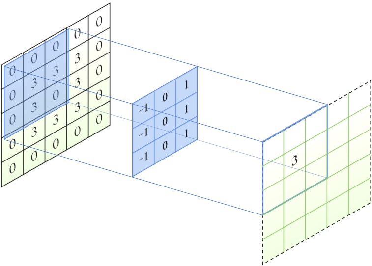
边缘检测的基本原理是利用图像中的亮度、颜色、纹理等差异,以及对象形状的不连续性,来检测图像中的边缘。常见的边缘检测算法包括 Prewitt、Sobel、Laplacian 等,这些算法可以生成一个边缘响应,图中每个像素点的值表示该位置周围边缘的强度。
在边缘检测算法中,使用被称为算子的矩阵,例如 Prewitt 算子、Sobel 算子、Laplacian 算子等。算子在输入图像上移动时,重叠的区域进行卷积运算,得到输出图像上某个位置的响应。

Prewitt 算子
Sobel 算子
Prewitt 边缘检测算法的优势在于它对噪声有一定的抑制作用,同时能够检测到图像中的水平和垂直边缘。然而,它对于其他方向的边缘检测效果较差。Sobel 检测算法对灰度渐变和噪声较多的边缘处理效果较好,但是对边缘的定位不够准确。
2 FPGA 布署与实现
2.1 功能与指标定义
使用紫光同创 FPGA 平台实现边缘检测功能,FPGA 需要实现的功能与指标如下:
(1)与电脑的串口通信,用于接收上位机下发的图像数据,波特率为 256000 Bd/s;
(2)RGB 转灰度图处理,使用 3 个乘法器对接收到的图像进行灰度转换,用于后续的边缘检测;
(3)Prewitt 边缘检测,使用 FPGA 内部的 RAM 资源缓存 3 行图像数据,对 3 × 3 邻域内的数据进行 Prewitt 边缘检测;
(4)DDR3 读写控制,将处理前后的图像数据分别写入 DDR3 的不同区域,实现图像的拼接;
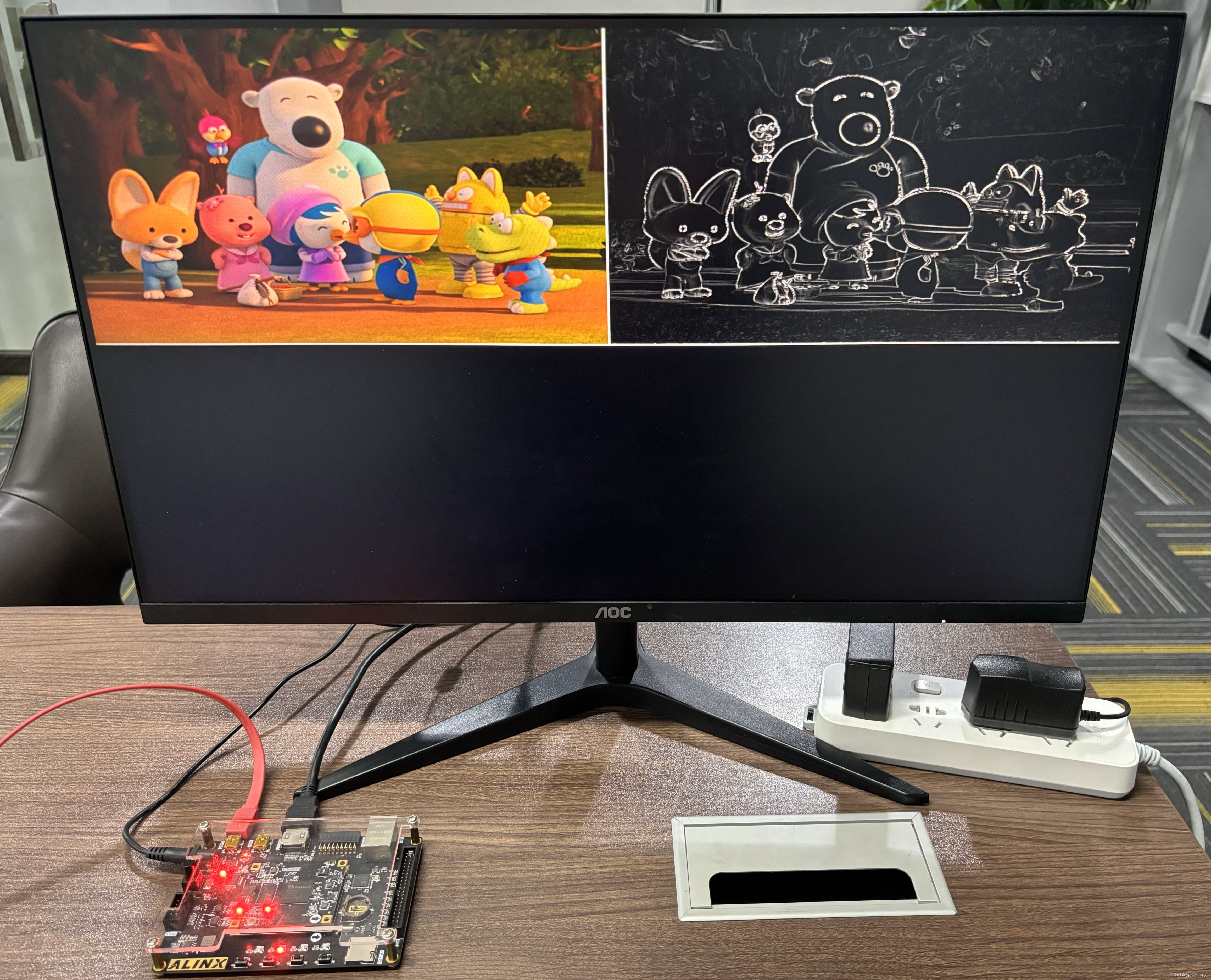
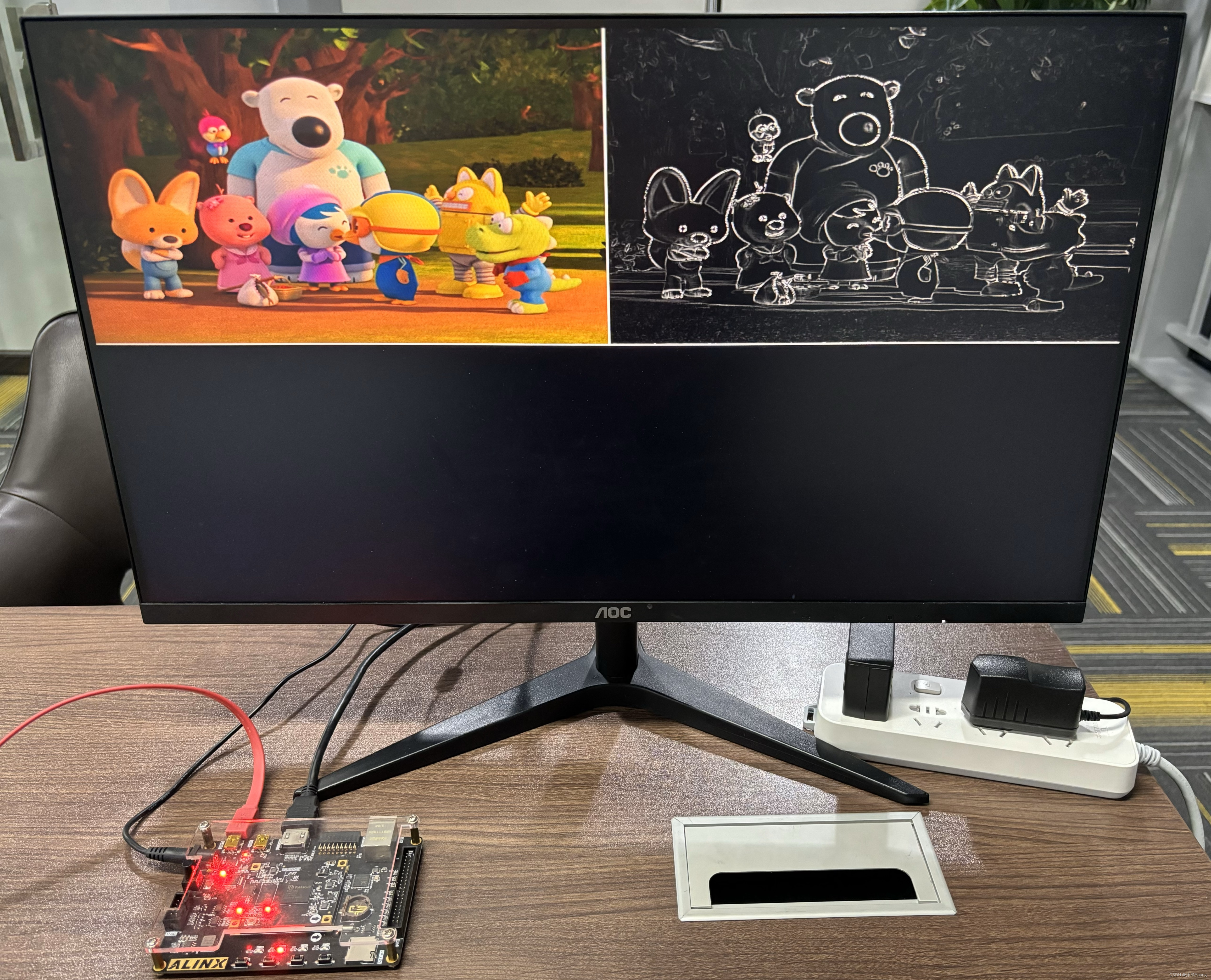
(5)HDMI 输出,输出一路 HDMI 信号源,用于将拼接后的图像显示在外接显示器上,分辨率为 1024×768。
2.2 模块设计
边缘检测工程主要的设计模块层次与功能说明如下:
| 模块名称 | 功能说明 | |
| top_uart | uart_rx_slice | 串口接收驱动模块 |
| uart_rx_parse | 串口数据解析模块,从上位机接收 8bit 原始图像,以及 Gamma 曲线数据 | |
| top_vidin | vidin_pipeline | pipeline 单元模块,缓存两行图像数据,并将数据提交到 ddr3 数据调度模块 |
| vidin_pipeline_s | pipeline 单元简化模块,只缓存两行图像数据,无需产生与提交 ddr3 写命令 | |
| conv_rgb2gray | RGB 转灰度图处理模块,使用乘法器进行灰度转换 | |
| conv_prewitt | 边缘检测模块,运用 Prewitt 算子对 3 × 3 领域内的数据进行处理 | |
| merge_out | dvi_timing_gen | HDMI 视频时序产生模块 |
| dvi_ddr_rd | 根据 HDMI 控制信号,提交读指令到 ddr3 数据调度模块 | |
| dvi_encoder | HDMI 输出编码(8b10b 编码)与输出驱动模块 | |
其中,conv_rgb2gray 模块实现灰度变换,conv_prewitt 模块实现边缘检测功能,conv_prewitt 实现水平边缘检测的思路为:
(1)对输入行数据进行打拍,得到 3 × 3 区域的数据;
(2)使用加法器电路,分别计算 3 × 3 区域内第 1 列、第 3 列的数据之和;
(3)使用比较器和减法器电路,计算第 1 列与第 3 列数据和的差。
对于垂直边缘检测,需要将列方向的数据求和,修改为行方向的数据求和。
conv_prewitt 模块代码如下:
`timescale 1 ns/ 1 psmodule conv_prewitt (input          reset,input          clock,input          load,input  [7:0]   ina,input  [7:0]   inb,input  [7:0]   inc,output [7:0]   edge_x,output [7:0]   edge_y
);// internal signal declarations
reg               load_r1;
reg               load_r2;
reg       [23:0]  pipeline_data1;
reg       [23:0]  pipeline_data2;
reg       [23:0]  pipeline_data3;reg       [15:0]  sum_of_col0;
reg       [15:0]  sum_of_col1;
reg       [15:0]  sum_of_col2;
reg       [15:0]  sum_of_row0;
reg       [15:0]  sum_of_row1;
reg       [15:0]  sum_of_row2;reg       [15:0]  buf_edge_x;
reg       [15:0]  buf_edge_y;// load 信号打两拍,用于边沿检测
always @(posedge reset or posedge clock) beginif (reset) beginload_r1 <= 1'b0;load_r2 <= 1'b0;endelse beginload_r1 <= load;load_r2 <= load_r1;end
end// 异步复位,同步复位
always @(posedge reset or posedge clock) beginif (reset) beginpipeline_data1 <= {3{8'h00}};pipeline_data2 <= {3{8'h00}};pipeline_data3 <= {3{8'h00}};endelse if (~load) beginpipeline_data1 <= {3{8'h00}};pipeline_data2 <= {3{8'h00}};pipeline_data3 <= {3{8'h00}};endelse beginpipeline_data1 <= {inc, inb, ina};pipeline_data2 <= pipeline_data1;pipeline_data3 <= pipeline_data2;end
end// 行、列求和
always @(posedge reset or posedge clock) beginif (reset) beginsum_of_col0 <= 16'd0;sum_of_col1 <= 16'd0;sum_of_col2 <= 16'd0;sum_of_row0 <= 16'd0;sum_of_row1 <= 16'd0;sum_of_row2 <= 16'd0;endelse beginsum_of_col0 <= pipeline_data1[0*8+:8] + pipeline_data1[1*8+:8] + pipeline_data1[2*8+:8];sum_of_col1 <= pipeline_data2[0*8+:8] + pipeline_data2[1*8+:8] + pipeline_data2[2*8+:8];sum_of_col2 <= pipeline_data3[0*8+:8] + pipeline_data3[1*8+:8] + pipeline_data3[2*8+:8];sum_of_row0 <= pipeline_data3[0*8+:8] + pipeline_data2[0*8+:8] + pipeline_data1[0*8+:8];sum_of_row1 <= pipeline_data3[1*8+:8] + pipeline_data2[1*8+:8] + pipeline_data1[1*8+:8];sum_of_row2 <= pipeline_data3[2*8+:8] + pipeline_data2[2*8+:8] + pipeline_data1[2*8+:8];end
endalways @(posedge reset or posedge clock) beginif (reset) beginbuf_edge_x <= 16'd0;buf_edge_y <= 16'd0;endelse beginif (sum_of_col2 >= sum_of_col0) buf_edge_x <= sum_of_col2 - sum_of_col0;else buf_edge_x <= sum_of_col0 - sum_of_col2;if (sum_of_row2 >= sum_of_row0) buf_edge_y <= sum_of_row2 - sum_of_row0;else buf_edge_y <= sum_of_row0 - sum_of_row2;end
endassign edge_x = buf_edge_x[0+:8];
assign edge_y = buf_edge_y[0+:8];endmodule
2.3 上板调试
使用 PyQt5 和 OpenCV 库编写上位机程序,通过串口发送原始图像数据。连接 HDMI 线和串口线,选择与发送图像,就可以看到 FPGA 的处理效果了 ~


)

 认识HarmonyOs)


在 Amazon SageMaker 上的动手实践(一))


— 算法模型优化和服务器部署)
)
 on i.MX RT1060 EVK - 1 “建立开发环境”)
