参考
AXI总线的Burst Type以及地址计算 | WRAP到底是怎么一回事?_axi wrap-CSDN博客
还有官方手册,名字太长想起来再写。
Transaction/Burst/Transfer/Beat
Transaction指一次传输事务,实际上包括了address phase, data phase与response phase,但由于AXI协议主要为data的传输服务,且AXI的data传输为burst-based,因此通常将Transaction与Burst等同。
Transfer是Burst的组成元素,一个Burst可以由一个或多个Transfer构成。而一个Beat指一拍,如果一个Transfer只需一拍,那么Transfer也可以等同于Beat。
总结:Transaction ≈ Burst > Transfer ≈ Beat。
对齐
根据对齐长度的不同,分为几类:
对单个transfer的num_of_bytes对齐,即start_addr可以被num_of_bytes整除,称为对齐传输、否则为非对齐传输。在非对齐传输中,可能会存在某些Byte无效的情况,通过STRB进行byte valid的标识。一般所说的对齐指的就是这种对齐。
对单个burst的总byte量(num_of_bytes * burst_len)对齐,
此时WRAP传输的start_addr = lower_bound_addr。即不存在到达上界回卷的情况,与INCR无异。这种对齐通常是用于计算WRAP的边界地址的。
参数
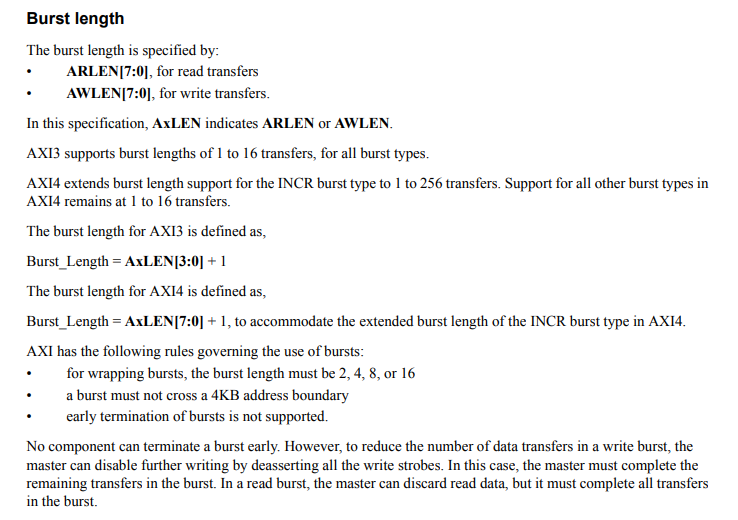
s_axi_awlen:Burst length
![]()
s_axi_awsize:Burst size
字节数 = 2^s_axi_awsize
如果 AXI 总线比突发大小更宽,则 AXI 接口必须根据传输地址确定每次传输要使用数据总线的哪些字节通道。请参见第 A3-52 页的数据读写结构。
任何传输的大小不得超过事务中任一代理的数据总线宽度
![]()
数值和
![]() 位宽挂钩。
位宽挂钩。


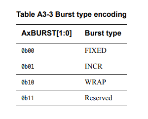
s_axi_awburst:Burst type
INCR最常用。其余的类似于交叉读写。
FIXED
In a fixed burst:
• The address is the same for every transfer in the burst.
• The byte lanes that are valid are constant for all beats in the burst. However, within those byte lanes, the actual bytes that have WSTRB asserted can differ for each beat in the burst.
This burst type is used for repeated accesses to the same location such as when loading or emptying a FIFO.
• 突发中每次传输的地址都相同。
• 有效的字节通道对于突发中的所有节拍都是恒定的。然而,在这些字节通道内,对于突发中的每个节拍,已置位 WSTRB 的实际字节可能有所不同。
此突发类型用于重复访问同一位置,例如加载或清空 FIFO 时。
- 同一个burst内每个transfer的地址保持一致。
- 同一个burst内byte lanes保持一致,但可以通过WSTRB选择每个transfer的有效bytes。
- 常用于对同一位置的重复访问,例如读或清空FIFO。
INCR
Incrementing.
In an incrementing burst, the address for each transfer in the burst is an increment of the address for the previous transfer. The increment value depends on the size of the transfer. For example, the address for each transfer in a burst with a size of four bytes is the previous address plus four.
This burst type is used for accesses to normal sequential memory
在递增突发中,突发中每次传输的地址是前一次传输的地址的增量。增量值取决于传输的大小。例如,大小为四个字节的突发中每次传输的地址是前一个地址加四。
这种突发类型用于访问正常的顺序内存。
- 同一个burst内地址随transfer递增。
- 地址递增量为一个transfer的大小。
- 常用于对normal sequential memory的访问。
WRAP
A wrapping burst is similar to an incrementing burst, except that the address wraps around to a lower address if an upper address limit is reached.
The following restrictions apply to wrapping bursts:
• the start address must be aligned to the size of each transfer
• the length of the burst must be 2, 4, 8, or 16 transfers.
The behavior of a wrapping burst is:
• The lowest address used by the burst is aligned to the total size of the data to be transferred, that is, to ((size of each transfer in the burst) × (number of transfers in the burst)). This address is defined as the wrap boundary.
• After each transfer, the address increments in the same way as for an INCR burst. However, if this incremented address is ((wrap boundary) + (total size of data to be transferred)) then the address wraps round to the wrap boundary.
• The first transfer in the burst can use an address that is higher than the wrap boundary, subject to the restrictions that apply to wrapping bursts. This means that the address wraps for any WRAP burst for which the first address is higher than the wrap boundary.
This burst type is used for cache line accesses.
回绕突发与递增突发类似,不同之处在于,如果达到地址上限,则地址回绕到较低地址。
以下限制适用于回绕突发:
• 起始地址必须与每次传输的大小对齐。
• 突发的长度必须为 2、4、8 或 16 个传输。
回绕突发的行为是:
• 突发使用的最低地址与要传输的数据的总大小对齐,
即与((突发中每次传输的大小)×(突发中传输的数量))对齐。
该地址被定义为回绕边界。
• 每次传输后,地址都会以与 INCR 突发相同的方式递增。
然而,如果这个递增的地址是((回绕边界)+(要传输的数据的总大小)),则该地址回绕到回绕边界。
• 突发中的第一次传输可以使用高于回绕边界的地址,但须遵守回绕突发的限制。这意味着对于第一个地址高于回绕边界的任何 WRAP 突发,地址会回绕。
这种突发类型用于高速缓存行访问。
start address需按照transfer的大小进行对齐(Align)。
burst length只能从2,4,8,16中取值。
地址递增达到upper boundary时回卷到lower boundary。upper boundary与lower boundary的地址计算在后文介绍。
通常用于从memory中读取cache line。
因为master对cache的访问通常是cache line中的某些bytes,但当发生cache miss时,从memory读回来的是整个cache line。而此时master发送的地址却不一定是cache line的起始地址,而起始地址可能位于中间,因此递增到upper boundary时需要回卷到lower boundary,才能将该cache line读完。
Burst address
本节提供了确定突发内传输的地址和字节通道的方法。这些方程使用以下变量:
Start_Address 主站发出的起始地址。
Number_Bytes 每次数据传输的最大字节数。
Data_Bus_Bytes 数据总线中的字节通道数。
Aligned_Address 起始地址的对齐版本。
Burst_Length 突发内的数据传输总数。
Address_N 突发传输N的地址。对于突发中的第一次传输,N 为 1。
Wrap_Boundary 回绕突发内的最低地址。
Lower_Byte_Lane 传输的最低寻址字节的字节通道。
Upper_Byte_Lane 传输的最高寻址字节的字节通道。
INT(x) x 的向下舍入的整数值。
这些方程确定突发内的传输地址:
• Start_Address = AxADDR
• Number_Bytes = 2 ^ AxSIZE
• Burst_Length = AxLEN + 1
• Aligned_Address = (INT(Start_Address / Number_Bytes) ) × Number_Bytes。
此等式确定突发中第一个传输的地址:
• Address_1 = Start_Address。
对于 INCR 突发以及地址未包装的 WRAP 突发,此等式确定突发中第一次传输后任何传输的地址:
• Address_N = Aligned_Address + (N – 1) × Number_Bytes。
对于WRAP 突发,Wrap_Boundary 变量定义回绕边界:
• Wrap_Boundary = (INT(Start_Address / (Number_Bytes × Burst_Length)))
× (Number_Bytes × Burst_Length)。
对于 WRAP 突发,如果
Address_N = Wrap_Boundary + (Number_Bytes × Burst_Length),
则:
• 对当前传输使用此等式:
— Address_N = Wrap_Boundary
• 对任何后续传输使用此等式:
— Address_N = Start_Address + ((N – 1) ) × Number_Bytes)
– (Number_Bytes × Burst_Length)。
这些公式确定突发中首次传输使用哪些字节通道:
• Lower_Byte_Lane = Start_Address –
(INT(Start_Address / Data_Bus_Bytes)) × Data_Bus_Bytes
• Upper_Byte_Lane = Aligned_Address + (Number_Bytes – 1) –
(INT(Start_Address / Data_Bus_Bytes)) × 数据总线字节。
这些公式确定突发中第一次传输后的所有传输使用哪些字节通道:
• Lower_Byte_Lane = Address_N –
(INT(Address_N / Data_Bus_Bytes)) × Data_Bus_Bytes
• Upper_Byte_Lane = Lower_Byte_Lane + Number_Bytes – 1。
数据传输至:
• DATA((8 × Upper_Byte_Lane) + 7 : (8 × Lower_Byte_Lane))。
s_axi_wstrb:Write strobes 写数据选通掩码
The WSTRB[n:0] signals when HIGH, specify the byte lanes of the data bus that contain valid information. There is one write strobe for each eight bits of the write data bus, therefore WSTRB[n] corresponds to WDATA[(8n)+7: (8n)].
WSTRB[n:0] 信号为高电平时,指定包含有效信息的数据总线的字节通道。写数据总线的每 8 位有 1 个写选通,因此 WSTRB[n] 对应于 WDATA[(8n)+7: (8n)]。
A master must ensure that the write strobes are HIGH only for byte lanes that contain valid data.
主设备必须确保仅对于包含有效数据的字节通道写选通为高电平。
When WVALID is LOW, the write strobes can take any value, although this specification recommends that they are either driven LOW or held at their previous value.
当 WVALID 为低电平时,写选通脉冲可以采用任何值,尽管本规范建议将它们驱动为低电平或保持在先前的值。
Narrow transfers窄传输
When a master generates a transfer that is narrower than its data bus, the address and control information determine which byte lanes the transfer uses:
当主设备生成比其数据总线窄的传输时,地址和控制信息决定传输使用哪些字节通道:
• in incrementing or wrapping bursts, different byte lanes are used on each beat of the burst
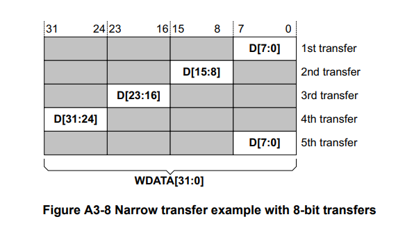
• in a fixed burst, the same byte lanes are used on each beat. Figure A3-8 and Figure A3-9 on page A3-53 give two examples of byte lanes use. The shaded cells indicate bytes that are not transferred.
• 在递增或回绕突发中,在突发的每个节拍上使用不同的字节通道。
• 在固定突发中,在每个节拍上使用相同的字节通道。 A3-53 页上的图 A3-8 和图 A3-9 给出了字节通道使用的两个示例。阴影单元表示未传输的字节。
In Figure A3-8
• the burst has five transfers
• the starting address is 0
• each transfer is eight bits
• the transfers are on a 32-bit bus
• the burst type is INCR.
Handshake process:握手机制
总结:写入数据的一方(作为主机时),在从机准备好接收数据的时候通过READY 信号提供数据,当准备好数据以后通过VALID来实现握手并且发送。
写地址,写数据,读地址:
主机——操作设备
从机——目标设备
写应答,读数据:
主机——操作设备
从机——目标设备
All five transaction channels use the same VALID/READY handshake process to transfer address, data, and control information.
This two-way flow control mechanism (双向流量控制机制)means both the master and slave can control the rate at which the information moves between master and slave.
The source generates the VALID signal to indicate when the address, data or control information is available. The destination generates the READY signal to indicate that it can accept the information. Transfer occurs only when both the VALID and READY signals are HIGH.
On master and slave interfaces there must be no combinatorial paths between input and output signals.
源生成 VALID 信号以指示地址、数据或控制信息何时可用。目的地生成 READY 信号以表明它可以接受信息。仅当 VALID 和 READY 信号均为高电平时才会发生传输。在主接口和从接口上,输入和输出信号之间不得存在组合路径。
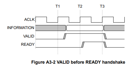
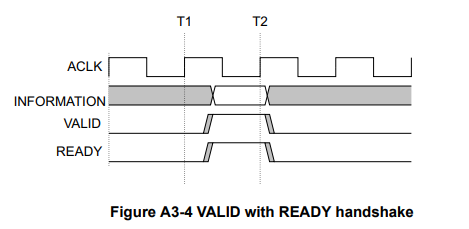
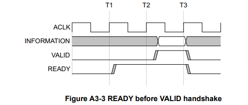
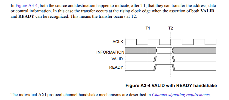
Figure A3-2 to Figure A3-4 on page A3-40 show examples of the handshake process.
In Figure A3-2, the source presents the address, data or control information after T1 and asserts the VALID signal.
A3-40 页上的图 A3-2 至图 A3-4 显示了握手过程的示例。在图 A3-2 中,源在 T1 后呈现地址、数据或控制信息并置位 VALID 信号。
The destination asserts the READY signal after T2, and the source must keep its information stable until the transfer occurs at T3, when this assertion is recognized.
目标端在 T2 之后断言 READY 信号,并且源端必须保持其信息稳定,直到 T3 发生传输(此时此断言被识别)。
不允许源等到 READY 置位后才置位 VALID。
一旦 VALID 被置位,它必须保持置位状态,直到握手发生,在时钟上升沿,VALID 和 READY 均被置位。
在图A3-3中,在T1之后,在地址、数据或控制信息有效之前,目的地断言READY,表明它可以接受该信息。源提供信息,并在 T2 之后断言“有效”,并且当该断言被识别时,传输发生在 T3。在这种情况下,传输发生在单个周期内。
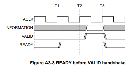
允许目的地在断言相应的 READY 之前等待 VALID 被断言。
如果断言 READY,则允许在断言 VALID 之前取消断言 READY。
在图A3-4中,在T1之后,源和目的地都恰好表明它们可以传输地址、数据或控制信息。在这种情况下,传输发生在时钟上升沿,此时可以识别 VALID 和 READY 的断言。这意味着转移发生在 T2。
通道握手信号
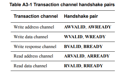
AXI协议下每个通道都有自己的 VALID/READY 握手信号对。
表 A3-1 显示了每个通道的信号。
写地址通道
主设备仅在驱动有效地址和控制信息时才能置位 AWVALID 信号。置位后,AWVALID 必须保持置位状态,直到从设备置位 AWREADY 后出现时钟上升沿。(反过来也成立)
AWREADY 的默认状态可以是高电平或低电平。本规范建议默认状态为高。当 AWREADY 为高电平时,从机必须能够接受提供给它的任何有效地址。
注:本规范不建议默认 AWREADY 状态为低电平,因为它强制传输至少需要两个周期,一个周期断言 AWVALID,另一个周期断言 AWREADY
写数据通道
在写突发期间,主机仅在驱动有效写数据时才能置位 WVALID 信号。置位后,WVALID 必须保持置位状态,直到从设备置位 WREADY 后出现时钟上升沿。
WREADY 的默认状态可以为高电平,但前提是从机始终可以在单个周期内接受写入数据。
主设备在驱动突发中的最终写传输时必须断言 WLAST 信号。
写响应通道
仅当从设备驱动有效的写响应时,它才能置位 BVALID 信号。置位后,BVALID 必须保持置位状态,直至主机置位 BREADY 后的时钟上升沿。BREADY 的默认状态可以为高电平,但前提是主器件始终可以在单个周期内接受写响应。
读地址通道
主设备仅在驱动有效地址和控制信息时才能置位 ARVALID 信号。置位后,ARVALID 必须保持置位状态,直到从设备置位 ARREADY 信号后出现时钟上升沿。
ARREADY 的默认状态可以是高电平或低电平。本规范建议默认状态为高。如果 ARREADY 为高电平,则从机必须能够接受提供给它的任何有效地址。
注意:本规范不建议默认 ARREADY 值为 LOW,因为它强制传输至少需要两个周期,一个周期用于断言 ARVALID,另一个周期用于断言 ARREADY。
读数据通道
从机仅在驱动有效读数据时才能置位 RVALID 信号。置位后,RVALID 必须保持置位状态,直到主机置位 RREADY 后的时钟上升沿。即使从机只有一个读数据源,它也必须仅在响应数据请求时断言 RVALID 信号。
主接口使用 RREADY 信号来指示它接受数据。 RREADY 的默认状态可以为高电平,但前提是主器件能够在启动读事务时立即接受读数据。
从设备在驱动突发中的最终读传输时必须断言 RLAST 信号。
具体时序
初始化完成:init_calib_complete
初始化完成,
即标志着SDRAM中的上电后的刷新,预充电,配置寄存器等行动的结束,可以对DDR3 SDRAM进行操作。

ui_clk_sync_rst,mmcm_locked没有复位完成,锁定相位前也不宜操作,但是他们的完成时间要远早于init_calib_complete,便可以不用太关心。
第一处握手:AW~写地址通道
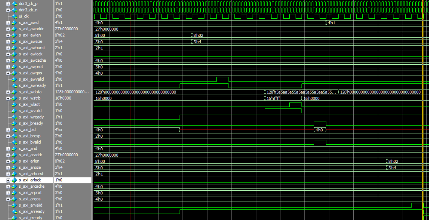
s_axi_awready期间准备好提供地址和各种配置信息,突发长度和突发尺寸等。
此处配置的是突发长度为3,突发尺寸为2^4=16个字节。
输入s_axi_awvalid的高电平表示发送数据(地址和各种配置信息)可用,
此时握手成立,
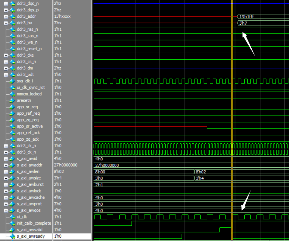
地址信息会在参考时钟的下一个上升沿发出。
可参考图A3-3
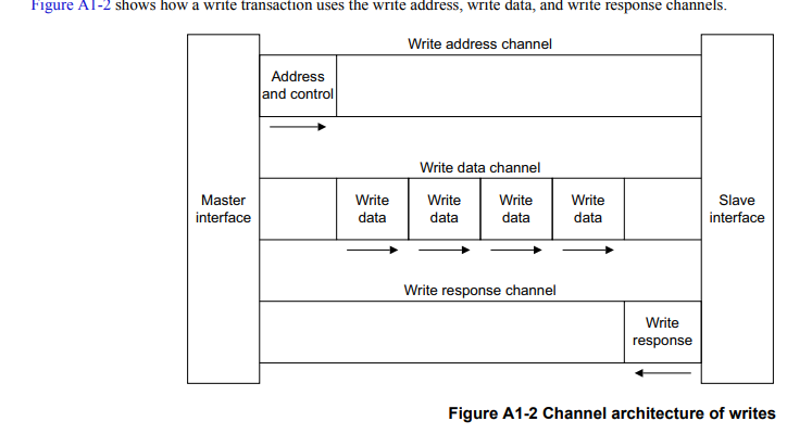
第二处握手:写数据通道
类似的,
s_axi_wready等待接收写入数据和选通脉冲,
s_axi_wvalid表示此时的写入数据和选通脉冲有效
s_axi_wlast表示最后一个brust的突发完成,也标志着s_axi_wvalid的结束。
同时握手结束。

一个用户时钟以后给予应答。
第三处握手:写应答通道
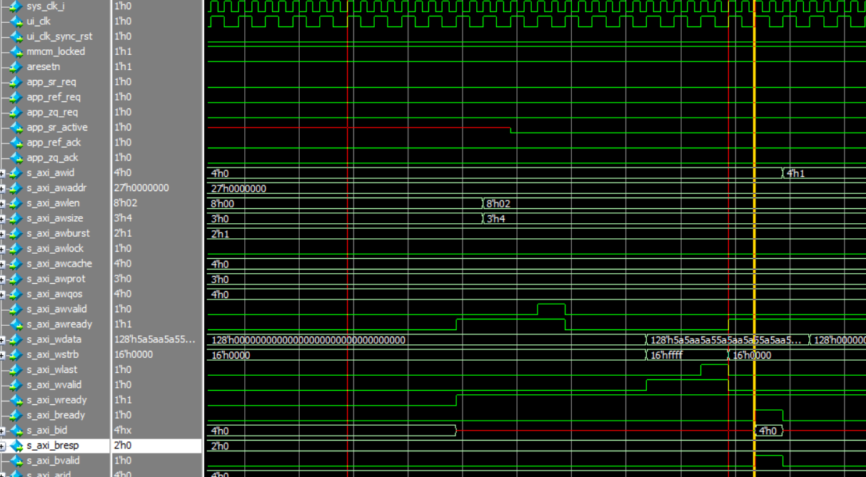
这一部分便完成了一个简单的Axi时序。
第四处握手:Ar~读地址通道
![]()
第五处握手:R~读数据通道

感慨:
本身工作频率就是倍频后的,而且上升下降都传数据,真的好快呀。


)
)

检测头结构创新,实现涨点 | 检测头新颖创新系列)


)
