前言:该项目实际上是在很多基础的小练习上合成起来的,例如涉及到uart(rs232)的数据传输、双fifo流水线操作、VGA图像显示,本次内容在此基础上又增添了sobel算法,能实现图像的边沿监测并VGA显示。
文章目录
- 1.项目描述
- 2.sobel算法解析:
- 3.模块结构示意图:
- 4.sobel_ctrl模块设计
- 4.1波形设计
- 4.2代码
- 5.VGA_shift模块设计
- 5.1 显示效果示意图:
- 5.2 简易波形示意图:
- 5.3 代码
- 6.uart_rx模块设计(直接用之前的设计 略)
- 7.顶层设计
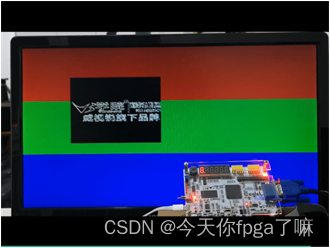
- 8.最终的显示效果:
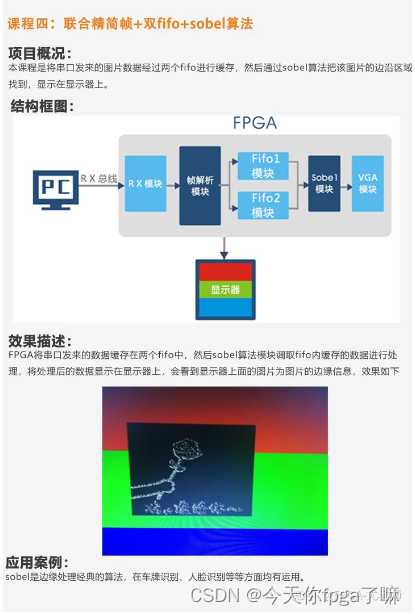
1.项目描述
通过串口助手把 200 行 x200 列数据传入 FPGA,对应三行三列的九个数进行 sobel算法,把边缘检测的结果(198x198的数据)通过 vga 来显示,用两种颜色来区分是否是边界点(边界用白色显示,其他用黑色)。
2.sobel算法解析:
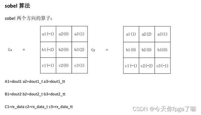
-
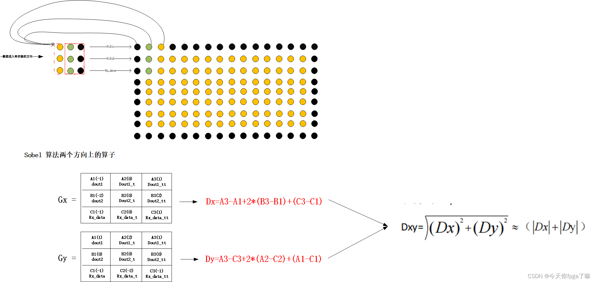
把图像每三行三列的数据分别乘上算子中对应位置的值再相加。然后进行如下运算,得到相应方向(x 和 y)的 Dx 和 Dy。
Dx=(a3-a1)+(b3-b1)*2+c3-c1;
Dy=(a1-c1)+(a2-c2)*2+a3-c3; -
对上面求得的 Dx 和 Dy 做平方和的平方根,再取近似值 Dx 和 Dy 的绝对值的和得到 Dxy:

-
如果 Dxy 的值大于一个阈值(这个阈值是多次尝试试出来的,本次项目中设置为5),表示该点为边界点,就让 VGA 显示一个白点,否则显示黑点。
-
把计算的结果通过 vga 显示,显示器会把是边界点的以白色像素显示,不是边界点的以黑色像素点显示,于是得到了一幅图像的轮廓
3.模块结构示意图:
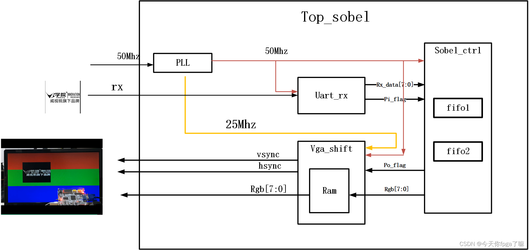
其中:
uart_rx模块在:手写一个uart协议——rs232
sobel_ctrl模块的核心是双fifo的流水线操作(需在此基础上进行改动):双fifo流水线操作
VGA_shift模块(原移动框为200x200 这里变成198x198,且添加了ram方便rgb图像的存储与读取):
4.sobel_ctrl模块设计
4.1波形设计
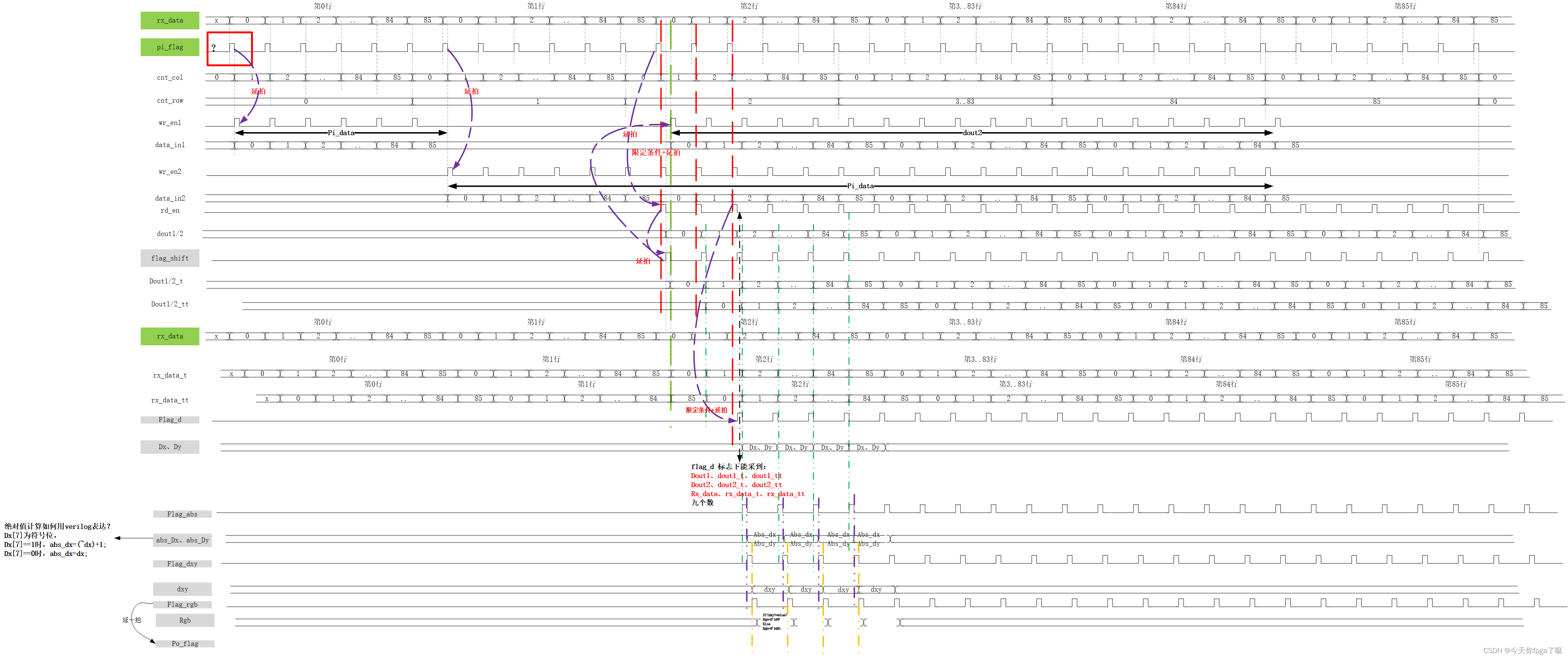
4.2代码
module sobel_ctrl(input wire clk,input wire rst,input wire [7:0] rx_data,input wire pi_flag,output reg [7:0] rgb,output reg po_flag);
reg[9:0] cnt_col,cnt_row;
reg wr_en1_r,wr_en2_r;
wire wr_en1,wr_en2;reg [7:0] data_in1_r;
wire [7:0] data_in1;
wire [7:0] dout1,dout2;reg [7:0] dout1_t,dout1_tt,dout2_t,dout2_tt;
reg [7:0] rx_data_t,rx_data_tt;
reg rd_en_r;
wire rd_en;reg shift_flag;reg flag_d;reg [7:0] Dx,Dy;reg flag_abs,flag_dxy,flag_rgb;
reg [7:0] abs_dx,abs_dy;
reg [7:0] dxy;parameter COL_MUX=199;
parameter ROW_MUX=199;
parameter VALUR=5;  //不断调试得到一个合适的阈值// cnt_col
always @(posedge clk) begin if(rst==1'b1) begincnt_col <= 'd0;end else if (pi_flag==1'b1 && cnt_col==COL_MUX) begincnt_col<='d0;endelse if (pi_flag==1'b1) begincnt_col<=cnt_col+1'b1;end
end// cnt_row
always @(posedge clk) begin if(rst==1'b1) begincnt_row <= 'd0;endelse if (cnt_row==ROW_MUX && pi_flag==1'b1 && cnt_col==COL_MUX) begincnt_row<='d0;endelse if (pi_flag==1'b1 && cnt_col==COL_MUX) begincnt_row<=cnt_row+1'b1;end
end// wr_en1_r
assign wr_en1=wr_en1_r;
always @(posedge clk) begin if(rst==1'b1) beginwr_en1_r <= 'd0;endelse if (cnt_row=='d0) beginwr_en1_r<=pi_flag;endelse if (cnt_row>'d1 && cnt_row<ROW_MUX) beginwr_en1_r<=shift_flag;end
end// wr_en2_r
assign wr_en2=wr_en2_r;
always @(posedge clk) begin if(rst==1'b1) beginwr_en2_r <= 'd0;end else if (cnt_row>'d0 && cnt_row<ROW_MUX) beginwr_en2_r<=pi_flag;endelsewr_en2_r<='d0;
end// data_in1_r
assign data_in1=data_in1_r;
always @(posedge clk) begin if(rst==1'b1) begindata_in1_r<= 'd0;end else if (cnt_row=='d0) begindata_in1_r<=rx_data;endelse if (cnt_row>'d1 && cnt_row<ROW_MUX) begindata_in1_r<=dout2;end
end// rd_en_r
assign rd_en=rd_en_r;always @(posedge clk) begin if(rst==1'b1) beginrd_en_r<= 'd0;end else if (cnt_row>'d1) beginrd_en_r<=pi_flag;endelse rd_en_r<='d0;
end// shift_flag
always @(posedge clk) begin if(rst==1'b1) beginshift_flag <= 'd0;end elseshift_flag<=rd_en_r;
end// dout1_t,dout1_tt,dout2_t,dout2_tt,rx_data_t,rx_data_tt
always @(posedge clk) begin if (shift_flag==1'b1) begin{dout1_tt,dout1_t}={dout1,dout1_t};{dout2_tt,dout2_t}={dout2,dout2_t};{rx_data_tt,rx_data_t}={rx_data_t,rx_data};end
endalways @(posedge clk) begin if(rst==1'b1) beginflag_d <= 'd0;end else if (cnt_row>=2 && cnt_col>2) beginflag_d<=rd_en_r;end
endalways @(posedge clk) begin if(rst==1'b1) beginDx <= 'd0;Dy <= 'd0;end else if (flag_d==1'b1) beginDx<=(dout1_tt-dout1)+(dout2_tt-dout2)<<1+(rx_data_tt-rx_data);Dy<=(dout1_tt-rx_data_tt)+(dout1_t-rx_data_t)<<1+(dout1-rx_data);endendalways @(posedge clk) begin if (rst==1'b1) beginflag_abs<='d0;flag_dxy<='d0;flag_rgb<='d0;po_flag<='d0;endelse{po_flag,flag_rgb,flag_dxy,flag_abs}<={flag_rgb,flag_dxy,flag_abs,flag_d};
end// abs_dx
always @(posedge clk) begin if(rst==1'b1) beginabs_dx<='d0;end else if (flag_abs==1'b1 ) beginif (dx[7]==1'b1) beginabs_dx<=(~Dx)+1'b1;endelseabs_dx<=Dx;end
end// abs_dy
always @(posedge clk) begin if(rst==1'b1) beginabs_dy <= 'd0;end else if (flag_abs==1'b1) beginif (dy[7]==1'b1) beginabs_dy<=(~Dy)+1'b1;endelse abs_dy<=Dy;end
end// dxy
always @(posedge clk) begin if(rst==1'b1) begindxy<= 'd0;end else if (flag_dxy==1'b1) begindxy<=abs_dx+abs_dy;end
end// rgb
always @(posedge clk) begin if(rst==1'b1) beginrgb <= 'd0;end else if (flag_rgb==1'b1) beginif (dxy>VALUR) beginrgb<=8'hff;endelsergb<=8'h00;end
endsfifo_8X256 sfifo1_8X256 (.clk(clk),      // input wire clk.din(data_in1),      // input wire [7 : 0] din.wr_en(wr_en1),  // input wire wr_en.rd_en(rd_en),  // input wire rd_en.dout(dout1),    // output wire [7 : 0] dout.full(),    // output wire full.empty()  // output wire empty
);sfifo_8X256 sfifo2_8X256 (.clk(clk),      // input wire clk.din(rx_data),      // input wire [7 : 0] din.wr_en(wr_en2),  // input wire wr_en.rd_en(rd_en),  // input wire rd_en_r.dout(dout2),    // output wire [7 : 0] dout.full(),    // output wire full.empty()  // output wire empty
);
endmodule
5.VGA_shift模块设计
5.1 显示效果示意图:
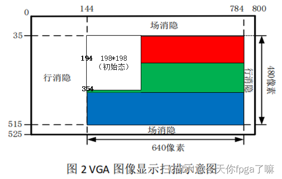
5.2 简易波形示意图:

5.3 代码
module vga_shift(input wire sclk,//50mhzinput wire clk_25,input wire rst,input wire [7:0] rgb_in,input wire pi_flag,output reg hsync,output reg vsync,output reg [7:0] rgb);parameter HSYNC_END=95;
parameter CNT_H_END=799;parameter VSYNC_END=1;
parameter CNT_V_END=524;parameter RED=8'b11100000;
parameter GREEN=8'b00011100;
parameter BLUE=8'b00000011;
parameter WHITE=8'b11111111;parameter ADDR_MUX=16'd39203;
reg [9:0] cnt_h;
reg [9:0] cnt_v;reg [8:0] x;
reg [8:0] y;reg flag_x;
reg flag_y;reg [15:0] addra,addrb;
wire [7:0] doutb;// cnt_halways @(posedge clk_25) begin if(rst==1'b1) begincnt_h<= 'd0;end else if (cnt_h==CNT_H_END) begincnt_h<='d0;endelse cnt_h<=cnt_h+1'b1;end // hsyncalways @(posedge clk_25) begin if(rst==1'b1) beginhsync<= 'd1;endelse if (cnt_h==CNT_H_END) beginhsync<='d1;end else if (cnt_h==HSYNC_END) beginhsync<='d0;endend// cnt_v
always @(posedge clk_25) begin if(rst==1'b1) begincnt_v <= 'd0;end else if (cnt_v==CNT_V_END && cnt_h==CNT_H_END) begincnt_v<='d0;endelse if (cnt_h==CNT_H_END) begincnt_v<=cnt_v+1'b1;end
end// vsync
always @(posedge clk_25) beginif(rst==1'b1) beginvsync <= 'd1;end else if (cnt_v==VSYNC_END && cnt_h==CNT_H_END) beginvsync<='d0;endelse if (cnt_v==CNT_V_END && cnt_h==CNT_H_END) beginvsync<='d1;endend
// x
always @(posedge clk_25) begin if(rst==1'b1) beginx <= 'd0;end else if (cnt_h==CNT_H_END && cnt_v==CNT_V_END && flag_x=='d0) beginx<=x+1'b1;endelse if (cnt_h==CNT_H_END && cnt_v==CNT_V_END && flag_x=='d1) beginx<=x-1'b1;end
end// flag_x
always @(posedge clk_25) begin if(rst==1'b1) beginflag_x<= 'd0;end else if (cnt_h==CNT_H_END && cnt_v==CNT_V_END && x=='d441 && flag_x=='d0) beginflag_x<='d1;endelse if (cnt_h==CNT_H_END && cnt_v==CNT_V_END && x=='d1 && flag_x=='d1) beginflag_x<='d0;end
end//y
always @(posedge clk_25) begin if(rst==1'b1) beginy<= 'd0;end else if (cnt_h==CNT_H_END && cnt_v==CNT_V_END && flag_y=='d0) beginy<=y+1'b1;end else if (cnt_h==CNT_H_END && cnt_v==CNT_V_END && flag_y=='d1) beginy<=y-1'b1;end
end// flag_y
always @(posedge clk_25) begin if(rst==1'b1) beginflag_y <= 'd0;end else if (cnt_h==CNT_H_END && cnt_v==CNT_V_END && y=='d281 && flag_y<='d0) beginflag_y<='d1;endelse if (cnt_h==CNT_H_END && cnt_v==CNT_V_END && y=='d1 && flag_y<='d1) beginflag_y<='d0;end
end// rgb
always @(posedge clk_25) begin if(rst=='b1) beginrgb<= 'd0;end//注意198x198像素时,白框范围需要改变else if (cnt_h>=144+x && cnt_h<=341+x && cnt_v>=35+y && cnt_v<=232+y) beginrgb<=doutb;endelse if (cnt_h>=144 && cnt_h<=783) beginif (cnt_v>=35 && cnt_v<=194) beginrgb<=RED;endelse if (cnt_v>=195 && cnt_v<=354) beginrgb<=GREEN;endelse if (cnt_v>=355 && cnt_v<=514) beginrgb<=BLUE;endend elsergb<='d0;end// addra  这里注意写ram的时钟为50mhz,读ram的时钟为25mhz(VGA的时钟)
always @(posedge sclk) begin if(rst) beginaddra<= 'd0;endelse if (pi_flag==1'b1 && addra==ADDR_MUX) beginaddra<='d0;endelse if (pi_flag==1'b1) beginaddra<=addra+1'b1;end end// addrb 注意ram读数据相对于读地址有一拍延迟,所以地址要早一拍给出
always @(posedge clk_25) begin if(rst==1'b1) beginaddrb <= 'd0;end else if (cnt_h>=144+x-1 && cnt_h<=341+x-1 && cnt_v>=35+y && cnt_v<=232+y && addrb==ADDR_MUX) beginaddrb<='d0;endelse if (cnt_h>=144+x-1 && cnt_h<=341+x-1 && cnt_v>=35+y && cnt_v<=232+y) beginaddrb<=addrb+1'b1;end
endasblk_mem_8x198x198 your_instance_name (.clka(sclk),    // input wire clka.wea(pi_flag),      // input wire [0 : 0] wea.addra(addra),  // input wire [15 : 0] addra.dina(rgb_in),    // input wire [7 : 0] dina.clkb(clk_25),    // input wire clkb.addrb(addrb),  // input wire [15 : 0] addrb.doutb(doutb)  // output wire [7 : 0] doutb
);endmodule
6.uart_rx模块设计(直接用之前的设计 略)
7.顶层设计
module top_sobel(input wire clk,//50mhzinput wire rst,input wire rx,output wire vsync,output wire hsync,output wire [7:0]rgb);wire clk_out25;
wire clk_out50;wire rx_data;
wire pi_flag_rx_to_sobel;
wire pi_flag_sobel_to_vga;wire [7:0] rgb_in;clk_wiz_gen25 instance_name(// Clock out ports.clk_out50(clk_out50),     // output clk_out50.clk_out25(clk_out25),     // output clk_out25// Clock in ports.clk_in50(clk));      // input clk_in50uart_rx inst_uart_rx (.clk     (clk_out50),.rst     (rst),.rx      (rx),.po_data (rx_data),.po_flag (pi_flag_rx_to_sobel));sobel_ctrl  inst_sobel_ctrl (.clk     (clk_out50),.rst     (rst),.rx_data (rx_data),.pi_flag (pi_flag_rx_to_sobel),.rgb     (rgb_in),.po_flag (pi_flag_sobel_to_vga));vga_shift inst_vga_shift (.sclk    (clk_out50),.clk_25  (clk_out25),.rst     (rst),.rgb_in  (rgb_in),.pi_flag (pi_flag_sobel_to_vga),.hsync   (hsync),.vsync   (vsync),.rgb     (rgb));endmodule
8.最终的显示效果:
上位机通过MATLAB处理,用友善助手下发原图像数据:

经过一系列图像处理后,最终在vga的显示效果:


)
)

)
)


2024.05.12:UCOSIII第六十六节:常用的控制宏介绍 第二部分)


服务器爆了)