知识改变命运,技术就是要分享,有问题随时联系,免费答疑,欢迎联系!

微思成立于2002年,是一个诚信敬业、积极向上、充满活力、专注技术服务的企业。
微思获得了八大厂商的培训授权,成长为福建地区广受认可的IT认证培训机构,同时也是知名的IT服务提供商及系统集成商,业务主要包含国际IT认证培训及考试、IT维护服务、系统集成。微思从成立开始,就把技术服务作为开展业务的主要根基,视技术服务为企业发展的生存命脉。微思拥有一批由工程师和讲师组成的出色技术团队,拥有8名CCIE、8名HCIE、5名OCP、8名MCITP、6名RHCE、5名VMware VCP、6名EMC/IBM存储/小型机工程师。到目前为止,微思已经投资超过2000万元建立备件库和体验中心,为本地客户提供优质的IT维护服务和完整的系统集成解决方案。
微思自成立以来,培养了一万多名IT专业人才!厦门85%大中型企业的IT技术人员都参加过微思的培训,同时,微思积累了丰富的就业渠道,为学员的就业提供有力的保障。
凭借良好技术和服务能力,微思完成了众多的IT建设项目,如建发集团、国贸集团、厦门航空、厦门银行、厦门邮储银行、乾照光电、三安集团、嵩屿码头、海润码头、海通码头、联想移动、安踏、七匹狼、九牧王、柒牌、特步、361度、厦门边检、厦门海关、厦门国检、厦门国土局、厦门地震局、厦门国家会计学院、厦门大学、华侨大学等,这些客户对微思的技术和服务给予了充分的肯定和良好的评价。
微思网络肩负“智造财富”的企业使命,凭借出色的技术实力、齐全的实验环境、高效的服务体系,为社会创造价值、为企业实现价值、为员工提升价值!
微思22年国际IT认证培训经验
红帽RHCE
OracleOCP
VMware VCP
信息安全CISP
项目管理PMP
华为 HCIA/HCIP/HCIE
思科CCNA/CCNP/CCIE
网络实战、云计算实战企业IT技术定制培训
数据中心解决方案
网络架构解决方案
网络安全解决方案
视频会议解决方案
集成业务咨询容灾备份解决方案服务器代理:华为/H3C/联想/DELL网络产品代理:华为/H3C/思科/锐捷存储产品代理:华为/H3C/联想/DELL安全产品代理:深信服/奇安信/网御
合作厂商:
思科、华为、H3C、锐捷、联想、DELL、VMware深信服、奇安信、网御星云、绿盟、启明、IBM、EMC
微思软实力
【集成资质】
| 华为金牌代理商 | 思科金牌代理商 |
| EMC金牌代理商 | NetApp金牌代理商 |
| VMware企业级代理商 | 数存金牌代理商 |
| 深信服金牌代理商 | 绿盟金牌代理商 |
| 天融信金牌代理商 | 北塔金牌代理商 |
| 联软金牌代理商 | 盈高金牌代理商 |
| Radware金牌代理商 | Panabit金牌代理商 |
【培训资质】
| 思科授权培训中心 | Oralce授权培训中心 |
| 华为授权培训中心 | VMware授权培训中心 |
| 红帽授权培训中心 | 微软授权培训中心 |
| 普尔文授权考试中心 | VUE授权考试中心 |
【微思优势】
| 专业的技术专家团队 | 22年国际IT认证培训经验 |
| 设备齐全的备件库 | 拥有资深专家讲师团队 |
| 丰富的系统集成经验 | 拥有专业的机房和网络实验室 |
| 完美的产品体验中心 | 百家名企合作丰富的就业渠道 |
微思硬实力
【八大厂商授权】

【三大上课教师,可同时容纳100+人】

实验平台使用方法
步骤:
- 安装VMware Workstation
- 安装EVE-NG客户端
- 关联SecureCRT
- 解压“微思网络CCNA实验平台”虚拟机
步骤1:安装VMware Workstation
双击VMware-workstation-full-15.5.1-15018445安装程序。

点击“下一步”。

勾选“我接受许可协议中的条款”,点击“下一步”。

安装位置使用默认路径即可,点击“下一步”。

按默认,点击“下一步”。

按默认,点击“下一步”。

点击“安装”。

程序正在安装,耐心等待。

点击“许可证”输入许可。

输入VMware-workstation-full-15.5.1-15018445-KEY记事本中的序列号,点击“输入”。

点击“完成”。

步骤2:安装EVE-NG客户端
双击EVE-NG-Win-Client-Pack-2.0安装程序。

点击“运行”。

点击“下一步”。

点击“下一步”。
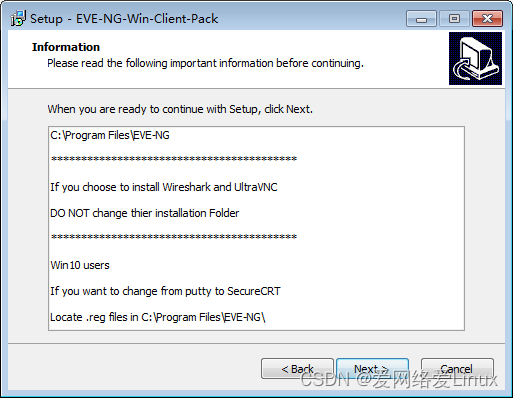
按默认即可,点击“下一步”


选中“I accept the agreement”,点击“Next”。

点击“Next”。
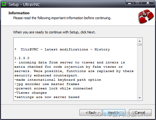
按默认即可,点击“Next”。

按默认即可,点击“Next”。

点击“Install”。


点击“Next”。

点击“Finish”。

安装Wireshark,点击“Next”

点击“I Agree”
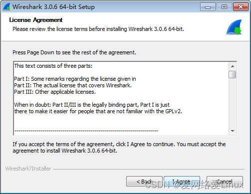
按默认即可,点击“Next”。

按默认即可,点击“Next”
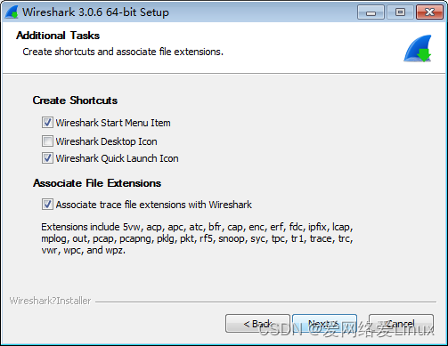
安装路径按默认即可,点击“Next”。

按默认即可,点击“Next”。
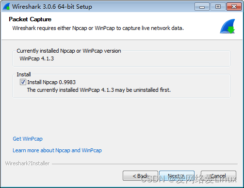
按默认即可,点击“Install”

点击“I Agree”

按默认即可,点击“Install”。
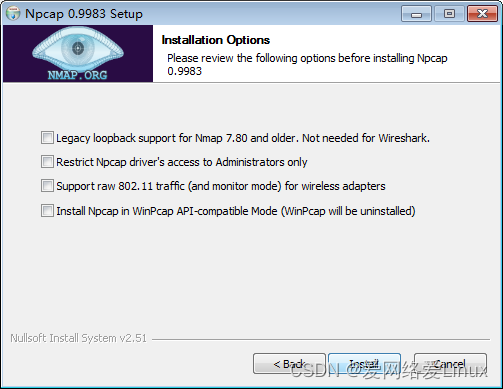
点击“Next”

点击“Finish”

点击“Next”

点击“Finish”
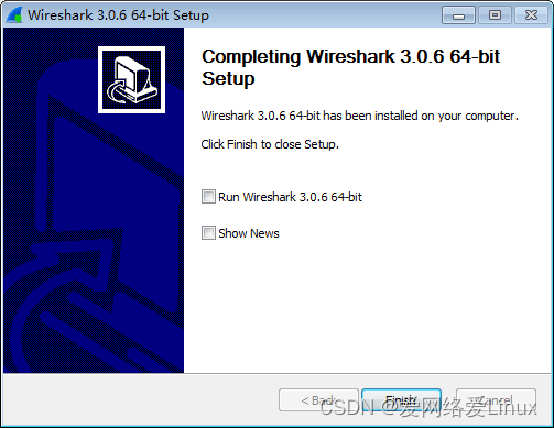
点击“Finish”

步骤3:关联SecureCRT
把“微思网络CCNA实验平台登录软件SecureCRT”压缩包解压到当前文件夹。

进入SecureCRT文件夹,找到“SecureCRT.exe”文件,鼠标右键“SecureCRT.exe”,点击发送到“桌面快捷方式”。

进入EVE-NG客户端的安装目录,默认在:C:\Program Files\EVE-NG,把注册表文件win10_64bit_sCRT.reg拷贝到其他盘,比如D盘。

鼠标右键D盘中的win10_64bit_sCRT.reg文件,单击“编辑”。

把SecureCRT的存放路径输入到箭头所指的地方(注意路径是双斜杠!!!),改完之后保存。
注意:SecureCRT的存放路径视具体情况而定,截图中的路径只是个例子!!!
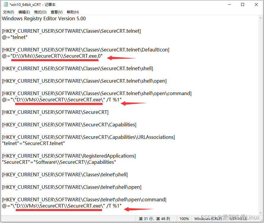
保存后,双击注册表文件win10_64bit_sCRT.reg,选择“是”即可。

步骤4:解压“微思网络CCNA实验平台”虚拟机
把“微思网络CCNA实验平台”压缩包解压到当前文件夹。

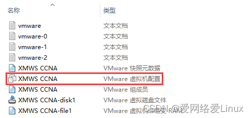
解压之后,进入VM XMWS CCNA文件夹,找到“VMware虚拟机配置”文件,然后双击运行。
此时,VMware Workstation会打开虚拟机XMWS CCNA。单击“开启此虚拟机”,打开虚拟机的电源。
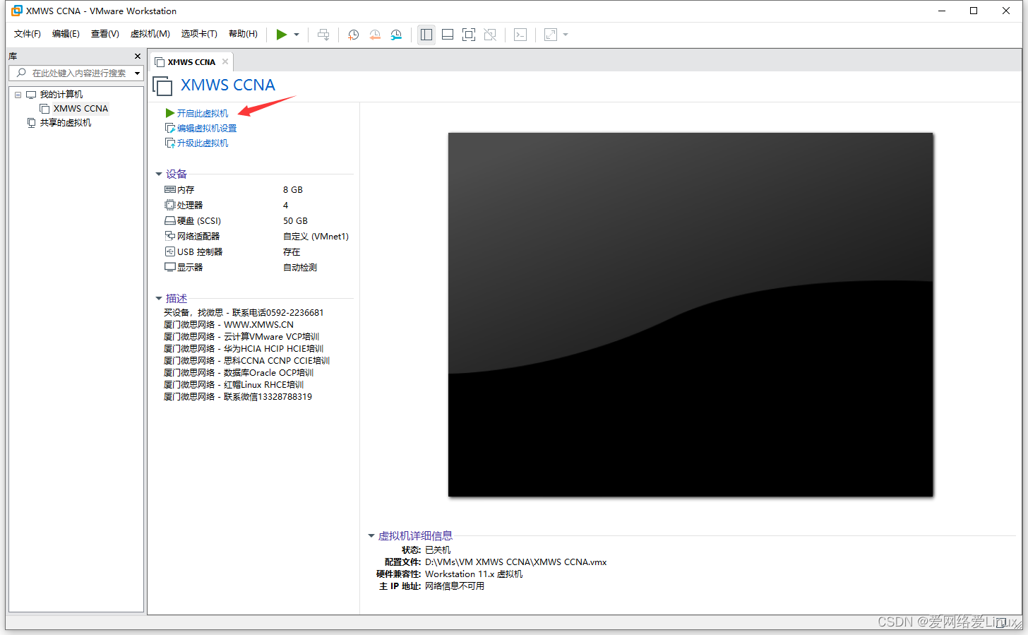
记录箭头所指的地方的IP地址。

在浏览器中输入上一步记录的IP地址,访问实验台;
用户名是:admin
密码是:www.xmws.cn

输入用户名和密码之后,点击“Sign In”登录实验台。

鼠标点击某个Lab之后,右边会有个“Open”按钮。

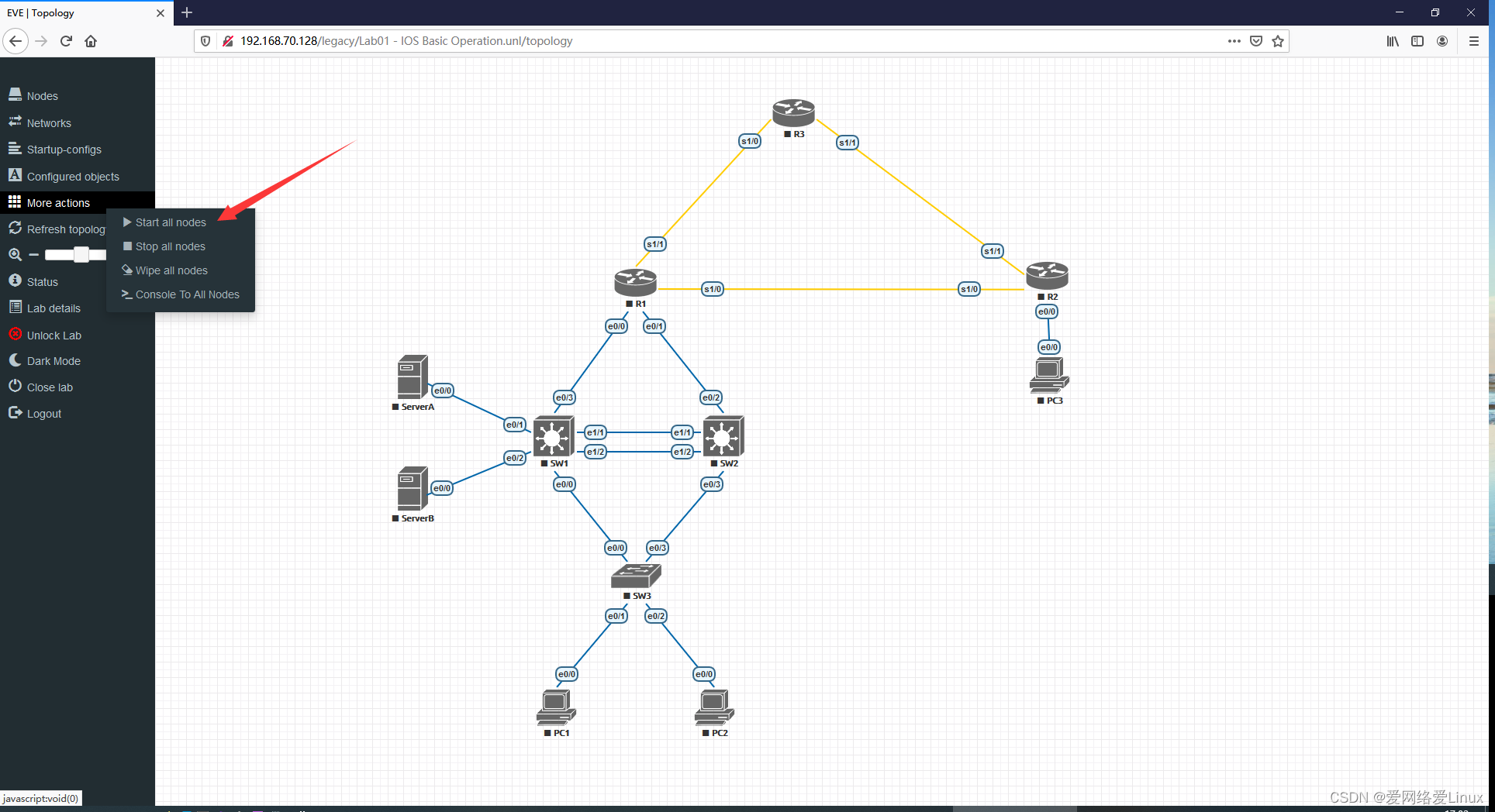
单击“Open”打开实验,鼠标移动到浏览器左侧,单击“More actions”,点击“Start all nodes”开启实验设备。
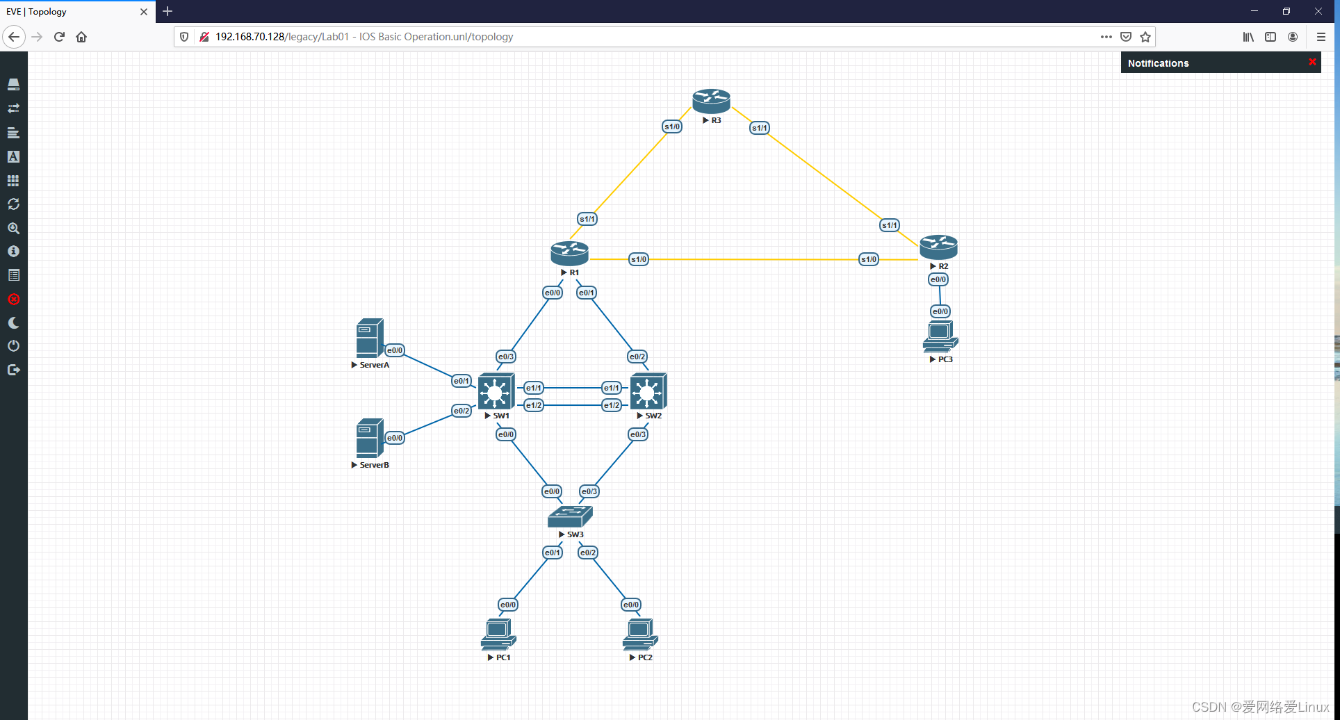
设备启动完成之后,图标颜色会变成蓝色,如下图所示。
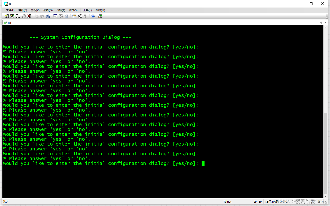
鼠标点击设备图标会自动关联SecureCRT,连续敲几下回车即可进入设备控制界面。
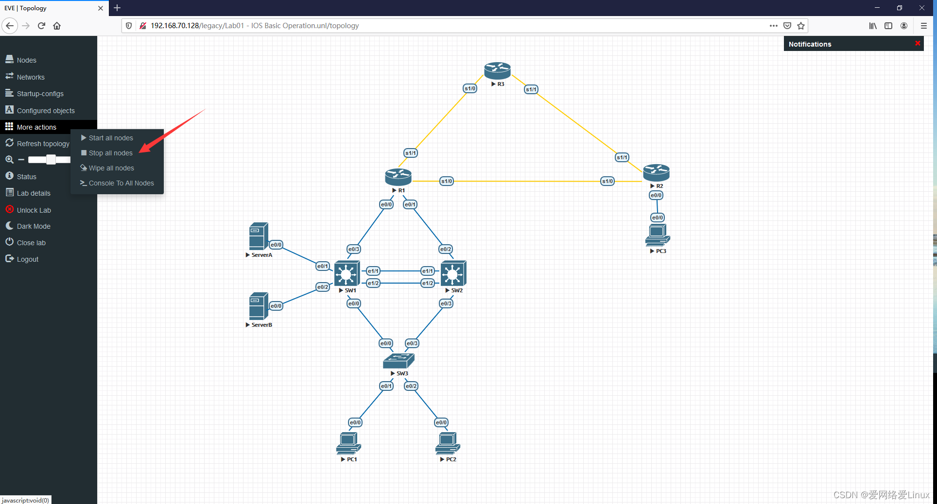
实验做完之后,鼠标移动到浏览器左侧,单击“More actions”,点击“Stop all nodes”关闭实验设备。
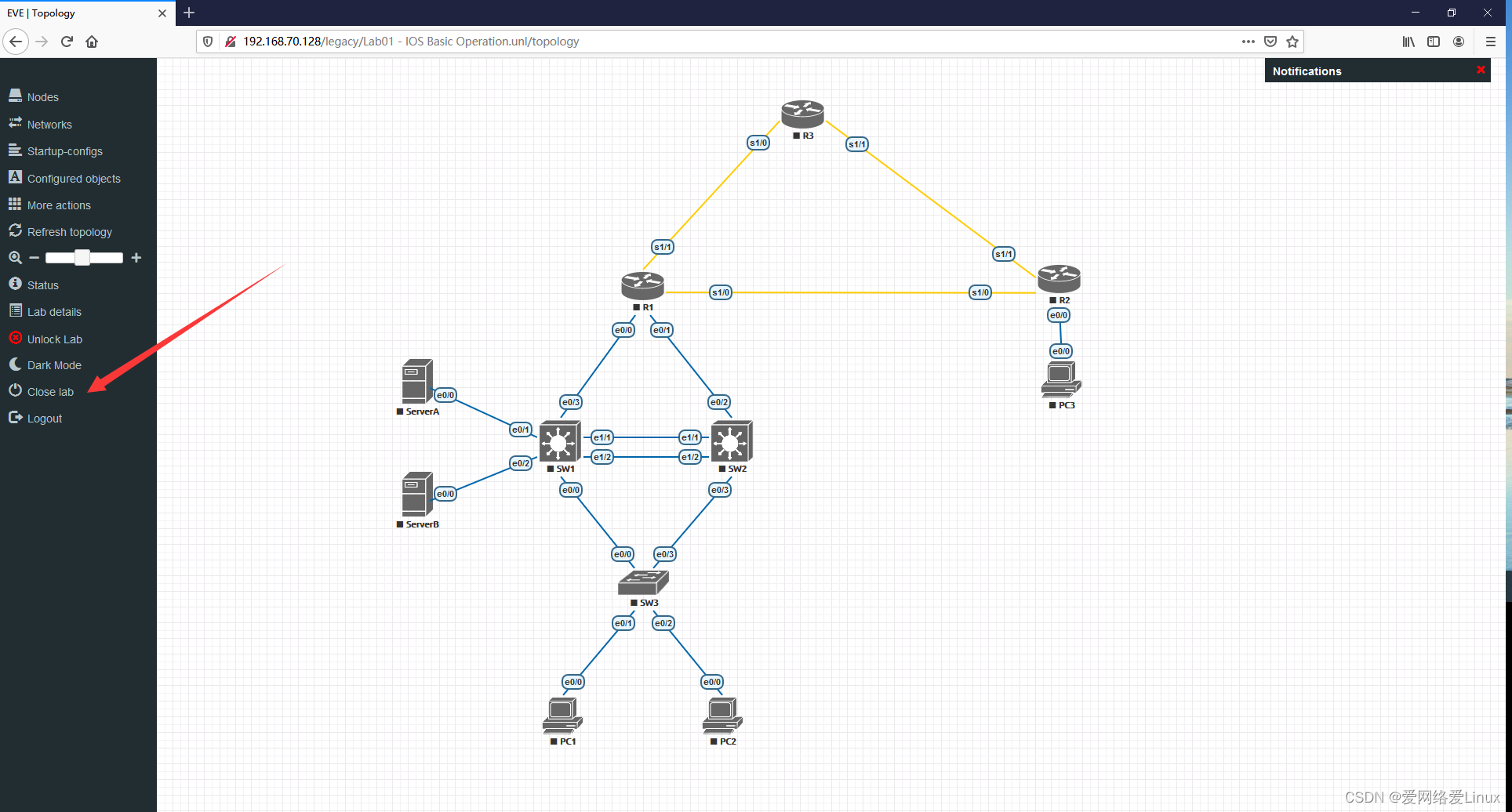
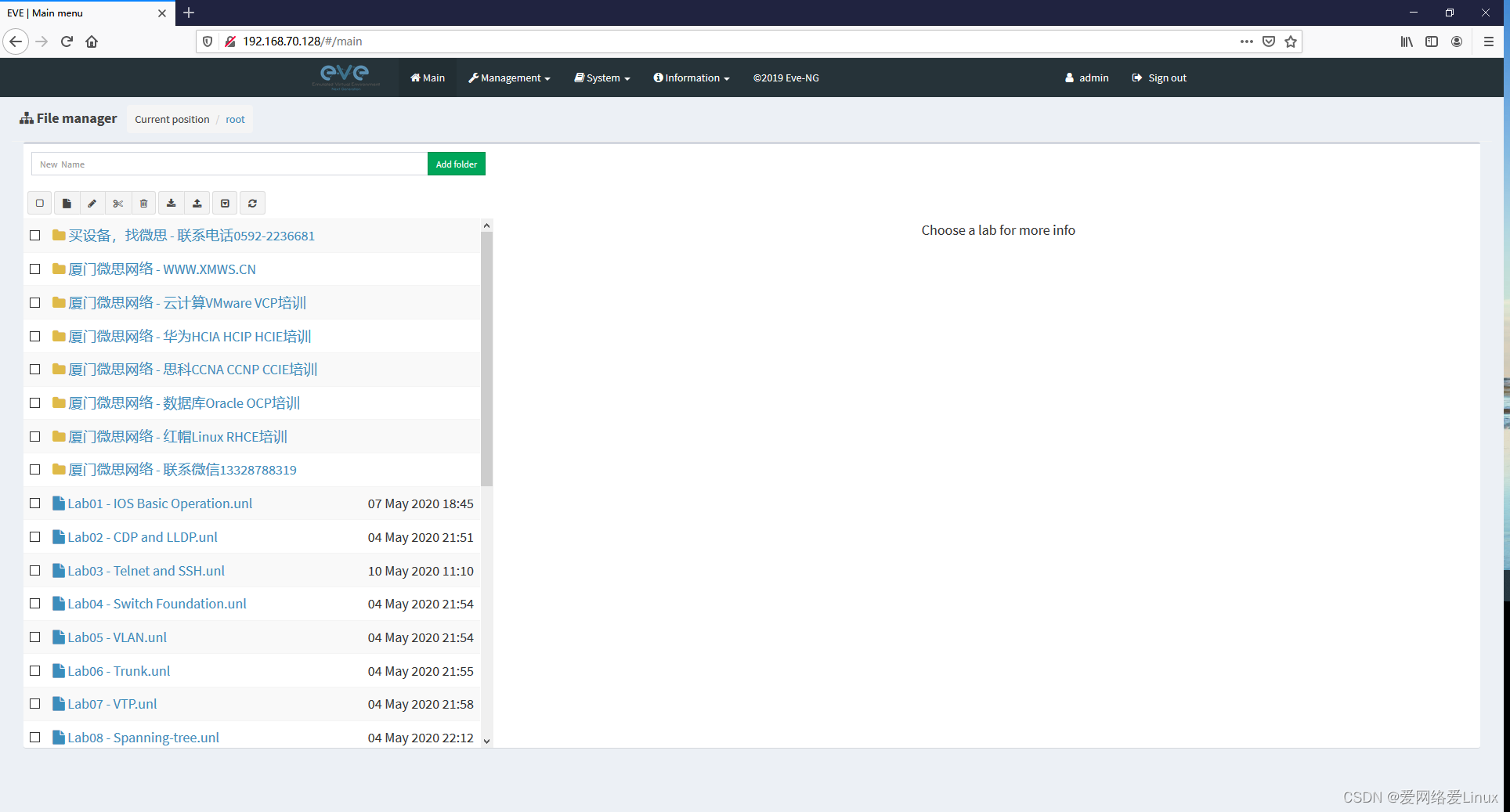
关闭实验台设备之后,鼠标移动到浏览器左侧,单击“Close lab”即可回到主页。
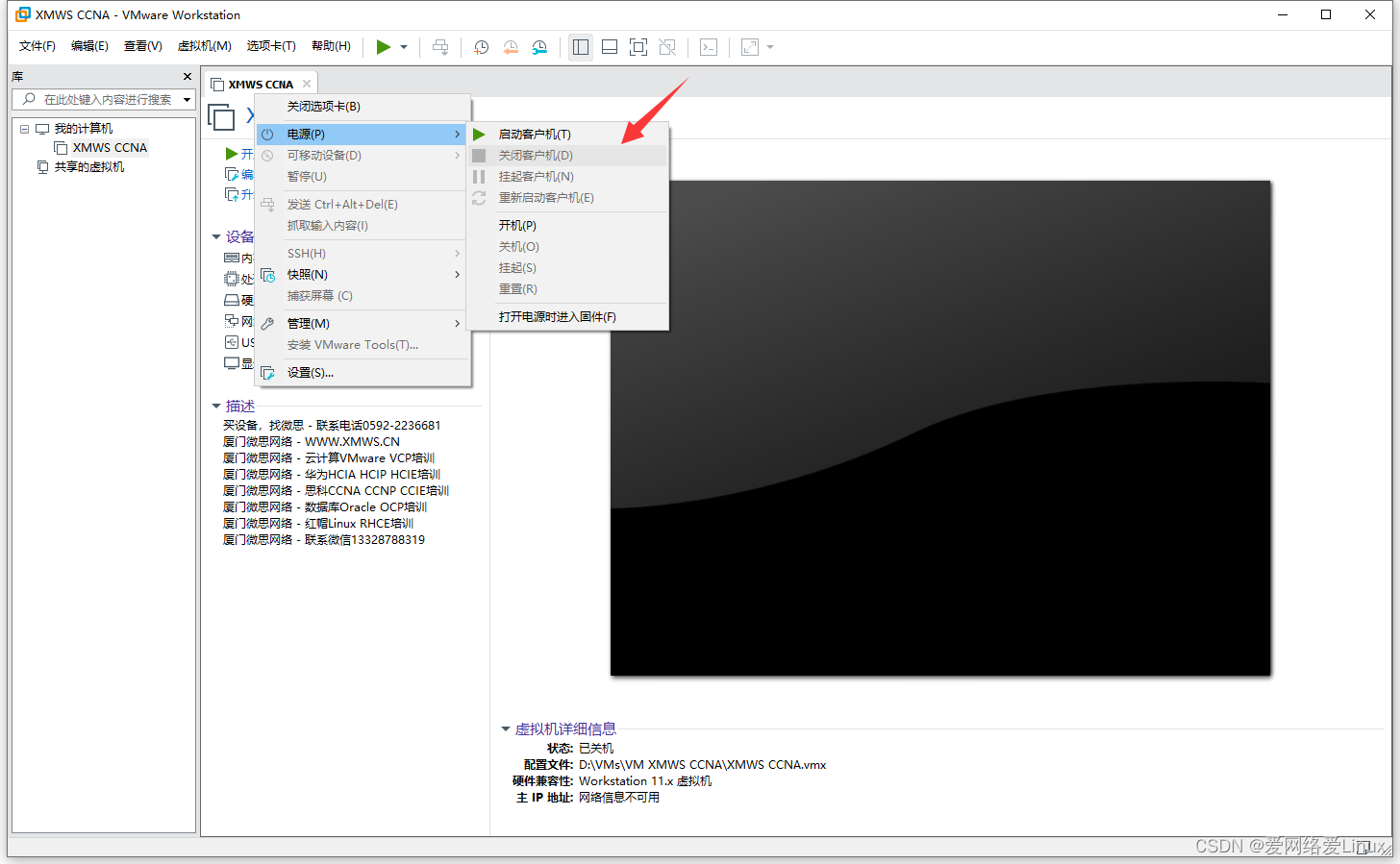
实验做完之后,鼠标右键虚拟机XMWS CCNA,单击“电源”,点击“关闭客户机”即可关闭虚拟机。
熟悉CISCO IOS的各个模式
Router> //用户模式
Router# //特权模式
Router(config-if)# //接口模式
Router(config-router)# //路由配置模式
Router(config-line)# //线路模式
Router(config-subif)# //子接口模式
Router> //用户模式
Router>enable //在用户模式敲enable进入特权模式
Router#disable //在特权模式敲disable退出到用户模式
Router>enable //在用户模式敲enable进入特权模式
Router#configure terminal //在特权模式敲入configure terminal进入到配置模式
Router(config)#interface ethernet0/0 //在配置模式敲入“interface+接口类型+接口编号”进入接口模式
Router(config-if)#exit //敲exit退出接口模式
Router(config)#router rip //敲“router + 路由协议”进入路由配置模式
Router(config-router)#exit //退出路由配置模式
Router(config)#line console 0 //进入线路模式
Router(config-line)#end //从线路模式退出(任何时候敲入end会退出到特权模式)
Router#configure terminal
Router(config)#interface ethernet 0/0.1 //进入子接口模式
Router(config-subif)#end //任何时候敲入end会退出到特权模式
Router#
熟悉CISCO IOS的基本配置
CISCO IOS常用配置命令
Router>enable
Router#configure terminal
Router(config)#enable secret xmws //设置enable的密码为xmws
Router(config)#enable password wisdom //设置enable的密码为wisdom,不能和enable secret 设置的密码相同,如果都设置,secret生效
Router(config)#no ip domain-lookup //关掉域名查找功能
Router(config)#service password-encryption //对明文口令进行加密,比如加密Console口、VTY或enable password设置的密码,这样密码不再显示为明文
Router(config)#line console 0 //进入Cconsole口
Router(config-line)#password xmws //设置Console口密码为xmws
Router(config-line)#login //启用密码
Router(config-line)#exec-timeout 0 0 //设置操作会话不超时
Router(config-line)#logging synchronous //配置光标跟随, 阻止控制台信息打断你当前的输入,从而使输入信息显得更为简单易读
Router(config)#line vty 0 4 //进入VTY
Router(config-line)#password cisco
Router(config-line)#login
Router(config-line)#exec-timeout 0 0
Router(config-line)#logging synchronous
注:VTY (虚拟终端) 在网络操作系统(包括Cisco IOS)中是一个接受telent或ssh连接的逻辑端口。
配置一台路由器当作PC使用
做实验时可以将路由器当作PC使用,用来测试网络的连通性等。
步骤:(本例子中当作PC的路由器接口为Ethernet 0/0)
- 关闭路由器的路由功能
- 设置接口IP地址
- 配置默认网关
- 检查
Router>enable
Router#configure terminal
Router(config)#hostname PC1
PC1(config)#no ip routing //关闭路由器的路由功能
PC1(config)#interface ethernet 0/0
PC1(config-if)#ip address 192.168.10.1 255.255.255.0 //配置接口IP地址
PC1(config-if)#no shutdown //激活接口
PC1(config-if)#exit
PC1(config)#ip default-gateway 192.168.10.254 //配置默认网关
PC1(config)#end
PC1#show ip interface brief //查看接口IP地址和状态
Interface IP-Address OK? Method Status Protocol
Ethernet0/0 10.1.1.1 YES manual up up
Ethernet0/1 unassigned YES unset administratively down down
Ethernet0/2 unassigned YES unset administratively down down
Ethernet0/3 unassigned YES unset administratively down down
PC1#show ip route //show ip route可以看到网关
Default gateway is 192.168.10.254
Host Gateway Last Use Total Uses Interface
ICMP redirect cache is empty
实验01:IOS基本配置
实验目的
- 熟悉CISCO IOS的常用模式
- 掌握CISCO IOS模式之间的切换
- 掌握CISCO IOS的基本配置命令
- 掌握如何把一台路由器配置成PC
实验拓扑

实验需求
- 根据实验拓扑图,完成设备的基本配置;
包括:主机名、Enable密码、关闭域名查找功能等;
- PC和Server使用路由器模拟,把路由器PC1、PC2、PC3、Server A、Server B配置成PC;
- 测试主机与网关,以及设备之间的网络连通性。
实验步骤
步骤1:路由器和交换机的基本配置
配置R1:
Router>enable
Router#configure terminal
Router(config)#hostname R1
R1(config)#enable password xmws
R1(config)#no ip domain-lookup
R1(config)#line console 0
R1(config-line)#password xmws
R1(config-line)#login
R1(config-line)#exec-timeout 0 0
R1(config-line)#logging synchronous
R1(config-line)#exit
R1(config)#line vty 0 4
R1(config-line)#password xmws
R1(config-line)#login
R1(config-line)#exec-timeout 0 0
R1(config-line)#logging synchronous
R1(config-line)#exit
R1(config)#interface serial1/0
R1(config-if)#ip address 10.1.12.1 255.255.255.0
R1(config-if)#no shutdown
R1(config-if)#exit
R1(config)#interface serial1/1
R1(config-if)#ip address 13.1.1.1 255.255.255.0
R1(config-if)#no shutdown
R1(config-if)#exit
R1(config)#interface ethernet0/0
R1(config-if)#ip address 192.168.10.254 255.255.255.0
R1(config-if)#no shutdown
R1(config-if)#exit
R1(config)#interface ethernet0/1
R1(config-if)#ip address 192.168.20.254 255.255.255.0
R1(config-if)#no shutdown
R1(config-if)#end
R1#
配置R2:
Router>enable
Router#configure terminal
Router(config)#hostname R2
R2(config)#enable password xmws
R2(config)#no ip domain-lookup
R2(config)#line console 0
R2(config-line)#password xmws
R2(config-line)#login
R2(config-line)#exec-timeout 0 0
R2(config-line)#logging synchronous
R2(config-line)#exit
R2(config)#line vty 0 4
R2(config-line)#password xmws
R2(config-line)#login
R2(config-line)#exec-timeout 0 0
R2(config-line)#logging synchronous
R2(config-line)#exit
R2(config)#interface serial1/0
R2(config-if)#ip address 10.1.12.2 255.255.255.0
R2(config-if)#no shutdown
R2(config-if)#exit
R2(config)#interface serial1/1
R2(config-if)#ip address 23.1.1.2 255.255.255.0
R2(config-if)#no shutdown
R2(config-if)#exit
R2(config)#interface ethernet0/0
R2(config-if)#ip address 172.16.1.254 255.255.255.0
R2(config-if)#no shutdown
R2(config-if)#end
R2#
配置R3:
Router>enable
Router#configure terminal
Router(config)#hostname R3conc
R3(config)#enable password xmws
R3(config)#no ip domain-lookup
R3(config)#line console 0
R3(config-line)#password xmws
R3(config-line)#login
R3(config-line)#exec-timeout 0 0
R3(config-line)#logging synchronous
R3(config-line)#exit
R3(config)#line vty 0 4
R3(config-line)#password xmws
R3(config-line)#login
R3(config-line)#exec-timeout 0 0
R3(config-line)#logging synchronous
R3(config-line)#exit
R3(config)#interface serial1/0
R3(config-if)#ip address 13.1.1.3 255.255.255.0
R3(config-if)#no shutdown
R3(config-if)#exit
R3(config)#interface serial1/1
R3(config-if)#ip address 23.1.1.3 255.255.255.0
R3(config-if)#no shutdown
R3(config-if)#exit
R3(config)#interface loopback0
R3(config-if)#ip address 9.2.6.7 255.255.255.255
R3(config-if)#end
R3#
配置SW1:
Switch>enable
Switch#configure terminal
Switch(config)#hostname SW1
SW1(config)#enable password xmws
SW1(config)#no ip domain-lookup
SW1(config)#line console 0
SW1(config-line)#password xmws
SW1(config-line)#login
SW1(config-line)#exec-timeout 0 0
SW1(config-line)#logging synchronous
SW1(config-line)#exit
SW1(config)#line vty 0 4
SW1(config-line)#password xmws
SW1(config-line)#login
SW1(config-line)#exec-timeout 0 0
SW1(config-line)#logging synchronous
SW1(config-line)#exit
SW1(config)#interface vlan 1
SW1(config-if)#ip address 192.168.10.11 255.255.255.0
SW1(config-if)#no shutdown
SW1(config-if)#exit
SW1(config)#ip default-gateway 192.168.10.254
SW1(config)#end
SW1#
配置SW2:
Switch>enable
Switch#configure terminal
Switch(config)#hostname SW2
SW2(config)#enable password xmws
SW2(config)#no ip domain-lookup
SW2(config)#line console 0
SW2(config-line)#password xmws
SW2(config-line)#login
SW2(config-line)#exec-timeout 0 0
SW2(config-line)#logging synchronous
SW2(config-line)#exit
SW2(config)#line vty 0 4
SW2(config-line)#password xmws
SW2(config-line)#login
SW2(config-line)#exec-timeout 0 0
SW2(config-line)#logging synchronous
SW2(config-line)#exit
SW2(config)#interface vlan 1
SW2(config-if)#ip address 192.168.10.12 255.255.255.0
SW2(config-if)#no shutdown
SW2(config-if)#exit
SW2(config)#ip default-gateway 192.168.10.254
SW2(config)#end
SW2#
配置SW3:
Switch>enable
Switch#configure terminal
Switch(config)#hostname SW3
SW3(config)#enable password xmws
SW3(config)#no ip domain-lookup
SW3(config)#line console 0
SW3(config-line)#password xmws
SW3(config-line)#login
SW3(config-line)#exec-timeout 0 0
SW3(config-line)#logging synchronous
SW3(config-line)#exit
SW3(config)#line vty 0 4
SW3(config-line)#password xmws
SW3(config-line)#login
SW3(config-line)#exec-timeout 0 0
SW3(config-line)#logging synchronous
SW3(config-line)#exit
SW3(config)#interface vlan 1
SW3(config-if)#ip address 192.168.10.13 255.255.255.0
SW3(config-if)#no shutdown
SW3(config-if)#exit
SW3(config)#ip default-gateway 192.168.10.254
SW3(config)#end
SW3#
步骤2:PC的基本配置
配置PC1:
Router>enable
Router#configure terminal
Router(config)#hostname PC1
PC1(config)#no ip routing
PC1(config)#ip default-gateway 192.168.10.254
PC1(config)#interface ethernet0/0
PC1(config-if)#ip address 192.168.10.1 255.255.255.0
PC1(config-if)#no shutdown
PC1(config-if)#end
PC1#
配置PC2:
Router>enable
Router#configure terminal
Router(config)#hostname PC2
PC2(config)#no ip routing
PC2(config)#ip default-gateway 192.168.10.254
PC2(config)#interface ethernet0/0
PC2(config-if)#ip address 192.168.10.2 255.255.255.0
PC2(config-if)#no shutdown
PC2(config-if)#end
PC2#
配置PC3:
Router>enable
Router#configure terminal
Router(config)#hostname PC3
PC3(config)#no ip routing
PC3(config)#ip default-gateway 172.16.1.254
PC3(config)#interface ethernet0/0
PC3(config-if)#ip address 172.16.1.1 255.255.255.0
PC3(config-if)#no shutdown
PC3(config-if)#end
PC3#
配置ServerA:
Router>enable
Router#configure terminal
Router(config)#hostname ServerA
ServerA(config)#no ip routing
ServerA(config)#ip default-gateway 192.168.10.254
ServerA(config)#interface ethernet0/0
ServerA(config-if)#ip address 192.168.10.3 255.255.255.0
ServerA(config-if)#no shutdown
ServerA(config-if)#end
ServerA#
配置PCB:
Router>enable
Router#configure terminal
Router(config)#hostname ServerB
ServerB(config)#no ip routing
ServerB(config)#ip default-gateway 192.168.10.254
ServerB(config)#interface ethernet0/0
ServerB(config-if)#ip address 192.168.10.4 255.255.255.0
ServerB(config-if)#no shutdown
ServerB(config-if)#end
ServerB#
实验检查
步骤1:检查路由器
检查R1:
R1#show ip interface brief
Interface IP-Address OK? Method Status Protocol
Ethernet0/0 192.168.10.254 YES manual up up
Ethernet0/1 192.168.20.254 YES manual up up
Ethernet0/2 unassigned YES unset administratively down down
Ethernet0/3 unassigned YES unset administratively down down
Serial1/0 10.1.12.1 YES manual up up
Serial1/1 13.1.1.1 YES manual up up
Serial1/2 unassigned YES unset administratively down down
Serial1/3 unassigned YES unset administratively down down
R1使用到的接口已经配置好IP地址,并且是up up状态。
检查R2:
R2#show ip interface brief
Interface IP-Address OK? Method Status Protocol
Ethernet0/0 172.16.1.254 YES manual up up
Ethernet0/1 unassigned YES unset administratively down down
Ethernet0/2 unassigned YES unset administratively down down
Ethernet0/3 unassigned YES unset administratively down down
Serial1/0 10.1.12.2 YES manual up up
Serial1/1 23.1.1.2 YES manual up up
Serial1/2 unassigned YES unset administratively down down
Serial1/3 unassigned YES unset administratively down down
R2使用到的接口已经配置好IP地址,并且是up up状态。
检查R3:
R3#show ip interface brief
Interface IP-Address OK? Method Status Protocol
Ethernet0/0 unassigned YES unset administratively down down
Ethernet0/1 unassigned YES unset administratively down down
Ethernet0/2 unassigned YES unset administratively down down
Ethernet0/3 unassigned YES unset administratively down down
Serial1/0 13.1.1.3 YES manual up up
Serial1/1 23.1.1.3 YES manual up up
Serial1/2 unassigned YES unset administratively down down
Serial1/3 unassigned YES unset administratively down down
Loopback0 9.2.6.7 YES manual up up
R3使用到的接口已经配置好IP地址,并且是up up状态。
步骤2:检查交换机
检查SW1:
SW1#show ip interface brief
Interface IP-Address OK? Method Status Protocol
Ethernet0/0 unassigned YES unset up up
Ethernet0/1 unassigned YES unset up up
Ethernet0/2 unassigned YES unset up up
Ethernet0/3 unassigned YES unset up up
Ethernet1/0 unassigned YES unset up up
Ethernet1/1 unassigned YES unset up up
Ethernet1/2 unassigned YES unset up up
Ethernet1/3 unassigned YES unset up up
Vlan1 192.168.10.11 YES manual up up
SW1的Vlan1接口已经配置好IP地址,并且是up up状态。
检查SW2:
Interface IP-Address OK? Method Status Protocol
Ethernet0/0 unassigned YES unset up up
Ethernet0/1 unassigned YES unset up up
Ethernet0/2 unassigned YES unset up up
Ethernet0/3 unassigned YES unset up up
Ethernet1/0 unassigned YES unset up up
Ethernet1/1 unassigned YES unset up up
Ethernet1/2 unassigned YES unset up up
Ethernet1/3 unassigned YES unset up up
Vlan1 192.168.10.12 YES manual up up
SW2的Vlan1接口已经配置好IP地址,并且是up up状态。
检查SW3:
SW3#show ip interface brief
Interface IP-Address OK? Method Status Protocol
Ethernet0/0 unassigned YES unset up up
Ethernet0/1 unassigned YES unset up up
Ethernet0/2 unassigned YES unset up up
Ethernet0/3 unassigned YES unset up up
Ethernet1/0 unassigned YES unset up up
Ethernet1/1 unassigned YES unset up up
Ethernet1/2 unassigned YES unset up up
Ethernet1/3 unassigned YES unset up up
Vlan1 192.168.10.13 YES manual up up
SW3的Vlan1接口已经配置好IP地址,并且是up up状态。
步骤3:检查PC
检查PC1:
PC1#show ip interface brief
Interface IP-Address OK? Method Status Protocol
Ethernet0/0 192.168.10.1 YES manual up up
Ethernet0/1 unassigned YES unset administratively down down
Ethernet0/2 unassigned YES unset administratively down down
Ethernet0/3 unassigned YES unset administratively down down
PC1已经配置好IP地址,并且是up up状态。
PC1#show ip route
Default gateway is 192.168.10.254
Host Gateway Last Use Total Uses Interface
ICMP redirect cache is empty
PC1的网关是192.168.10.254。
检查PC2:
PC2#show ip interface brief
Interface IP-Address OK? Method Status Protocol
Ethernet0/0 192.168.10.2 YES manual up up
Ethernet0/1 unassigned YES unset administratively down down
Ethernet0/2 unassigned YES unset administratively down down
Ethernet0/3 unassigned YES unset administratively down down
PC2已经配置好IP地址,并且是up up状态。
PC2#show ip route
Default gateway is 192.168.10.254
Host Gateway Last Use Total Uses Interface
ICMP redirect cache is empty
PC2的网关是192.168.10.254。
检查PC3:
PC3#show ip interface brief
Interface IP-Address OK? Method Status Protocol
Ethernet0/0 172.16.1.1 YES manual up up
Ethernet0/1 unassigned YES unset administratively down down
Ethernet0/2 unassigned YES unset administratively down down
Ethernet0/3 unassigned YES unset administratively down down
PC3已经配置好IP地址,并且是up up状态。
PC3#show ip route
Default gateway is 172.16.1.254
Host Gateway Last Use Total Uses Interface
ICMP redirect cache is empty
PC3的网关是172.16.1.254。
检查ServerA:
ServerA#show ip interface brief
Interface IP-Address OK? Method Status Protocol
Ethernet0/0 192.168.10.3 YES manual up up
Ethernet0/1 unassigned YES unset administratively down down
Ethernet0/2 unassigned YES unset administratively down down
Ethernet0/3 unassigned YES unset administratively down down
ServerA已经配置好IP地址,并且是up up状态。
ServerA#show ip route
Default gateway is 192.168.10.254
Host Gateway Last Use Total Uses Interface
ICMP redirect cache is empty
ServerA的网关是192.168.10.254。
检查ServerB:
ServerB#show ip interface brief
Interface IP-Address OK? Method Status Protocol
Ethernet0/0 192.168.10.4 YES manual up up
Ethernet0/1 unassigned YES unset administratively down down
Ethernet0/2 unassigned YES unset administratively down down
Ethernet0/3 unassigned YES unset administratively down down
ServerB已经配置好IP地址,并且是up up状态。
ServerB#show ip route
Default gateway is 192.168.10.254
Host Gateway Last Use Total Uses Interface
ICMP redirect cache is empty
ServerB的网关是192.168.10.254。
连通性测试
步骤1:测试PC和网关的连通性
测试PC1:
PC1#ping 192.168.10.254
Type escape sequence to abort.
Sending 5, 100-byte ICMP Echos to 192.168.10.254, timeout is 2 seconds:
!!!!!
Success rate is 100 percent (5/5), round-trip min/avg/max = 1/203/1012 ms
PC1跟网关的连通性正常。
测试PC2:
PC2#ping 192.168.10.254
Type escape sequence to abort.
Sending 5, 100-byte ICMP Echos to 192.168.10.254, timeout is 2 seconds:
!!!!!
Success rate is 100 percent (5/5), round-trip min/avg/max = 1/203/1011 ms
PC2跟网关的连通性正常。
测试PC3:
PC3#ping 172.16.1.254
Type escape sequence to abort.
Sending 5, 100-byte ICMP Echos to 172.16.1.254, timeout is 2 seconds:
!!!!!
Success rate is 100 percent (5/5), round-trip min/avg/max = 1/201/1002 ms
PC3跟网关的连通性正常。
测试ServerA:
ServerA#ping 192.168.10.254
Type escape sequence to abort.
Sending 5, 100-byte ICMP Echos to 192.168.10.254, timeout is 2 seconds:
!!!!!
Success rate is 100 percent (5/5), round-trip min/avg/max = 1/202/1009 ms
ServerA跟网关的连通性正常。
测试ServerB:
ServerB#ping 192.168.10.254
Type escape sequence to abort.
Sending 5, 100-byte ICMP Echos to 192.168.10.254, timeout is 2 seconds:
!!!!!
Success rate is 100 percent (5/5), round-trip min/avg/max = 1/202/1006 ms
ServerB跟网关的连通性正常。
步骤2:测试交换机和网关的连通性
测试SW1:
SW1#ping 192.168.10.254
Type escape sequence to abort.
Sending 5, 100-byte ICMP Echos to 192.168.10.254, timeout is 2 seconds:
!!!!!
Success rate is 100 percent (5/5), round-trip min/avg/max = 1/1/2 ms
SW1跟网关的连通性正常。
测试SW2:
SW2#ping 192.168.10.254
Type escape sequence to abort.
Sending 5, 100-byte ICMP Echos to 192.168.10.254, timeout is 2 seconds:
!!!!!
Success rate is 100 percent (5/5), round-trip min/avg/max = 1/1/2 ms
SW2跟网关的连通性正常。
测试SW3:
SW3#ping 192.168.10.254
Type escape sequence to abort.
Sending 5, 100-byte ICMP Echos to 192.168.10.254, timeout is 2 seconds:
!!!!!
Success rate is 100 percent (5/5), round-trip min/avg/max = 1/1/1 ms
SW3跟网关的连通性正常。
步骤3:测试路由器之间链路的连通性
测试R1和R2之间链路:
R1#ping 10.1.12.2
Type escape sequence to abort.
Sending 5, 100-byte ICMP Echos to 10.1.12.2, timeout is 2 seconds:
!!!!!
Success rate is 100 percent (5/5), round-trip min/avg/max = 5/9/10 ms
R1和R2之间的连通性正常。
测试R1和R3之间的链路:
R1#ping 13.1.1.3
Type escape sequence to abort.
Sending 5, 100-byte ICMP Echos to 13.1.1.3, timeout is 2 seconds:
!!!!!
Success rate is 100 percent (5/5), round-trip min/avg/max = 9/10/11 ms
R1和R3之间的连通性正常。
测试R2和R3之间的链路:
R2#ping 23.1.1.3
Type escape sequence to abort.
Sending 5, 100-byte ICMP Echos to 23.1.1.3, timeout is 2 seconds:
!!!!!
Success rate is 100 percent (5/5), round-trip min/avg/max = 8/9/11 ms
R2和R3之间的连通性正常。
实验02:配置Telnet与SSH
实验目的
- 理解Telnet与SSH的运行原理
- 掌握Telnet与SSH的配置方法
实验拓扑
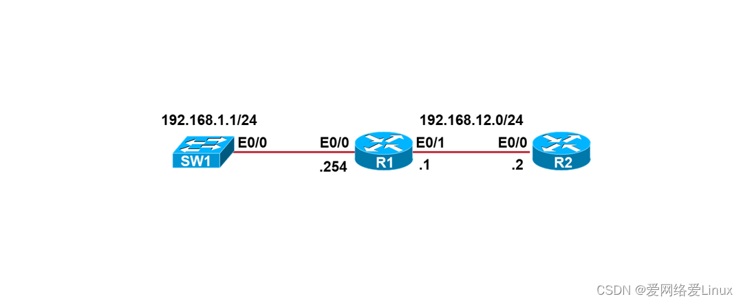
实验需求
- 根据实验拓扑图,完成设备的基本配置;
- SW1允许R1通过Telnet远程管理,VTY密码为xmws;
- R2允许R1通过SSH version2远程管理,用户名为xmws,密码为wisdom,域名为xmws.cn。
实验步骤
步骤1:设备的基本配置
配置R1:
Router>enable
Router#configure terminal
Router(config)#hostname R1
R1(config)#no ip domain-lookup
R1(config)#line console 0
R1(config-line)#exec-timeout 0 0
R1(config-line)#logging synchronous
R1(config-line)#exit
R1(config)#enable password xmws
R1(config)#interface ethernet0/0
R1(config-if)#ip address 192.168.1.254 255.255.255.0
R1(config-if)#no shutdown
R1(config-if)#exit
R1(config)#interface ethernet0/1
R1(config-if)#ip address 192.168.12.1 255.255.255.0
R1(config-if)#no shutdown
R1(config-if)#end
R1#
配置R2:
Router>enable
Router#configure terminal
Router(config)#hostname R2
R2(config)#no ip domain-lookup
R2(config)#line console 0
R2(config-line)#exec-timeout 0 0
R2(config-line)#logging synchronous
R2(config-line)#exit
R2(config)#enable password xmws
R2(config)#interface ethernet0/0
R2(config-if)#ip address 192.168.12.2 255.255.255.0
R2(config-if)#no shutdown
R2(config-if)#end
R2#
配置SW1:
Switch>enable
Switch#configure terminal
Switch(config)#hostname SW1
SW1(config)#no ip domain-lookup
SW1(config)#line console 0
SW1(config-line)#exec-timeout 0 0
SW1(config-line)#logging synchronous
SW1(config-line)#exit
SW1(config)#enable password xmws //必须设置,否则Telnet上SW1后无法进入特权模式
SW1(config)#interface vlan 1
SW1(config-if)#ip address 192.168.1.1 255.255.255.0
SW1(config-if)#no shutdown
SW1(config-if)#exit
SW1(config)#ip default-gateway 192.168.1.254
SW1(config)#end
SW1#
步骤2:配置Telnet
配置SW1:
SW1>enable
SW1#configure terminal
SW1(config)#line vty 0 4 //进入VTY
SW1(config-line)#password xmws //设置Telnet登录的密码为xmws
SW1(config-line)#login //启用密码
SW1(config-line)#transport input telnet //允许通过Telnet远程登录
SW1(config-line)#end
SW1#
步骤3:配置SSH
配置R2:
R2>enable
R2#configure terminal
R2(config)#username xmws password wisdom //创建用户名和密码
R2(config)#ip ssh version 2 //启用SSH版本2
R2(config)#ip domain-name xmws.cn //定义域名
R2(config)#crypto key generate rsa //生成密钥
The name for the keys will be: R2.xmws.cn
Choose the size of the key modulus in the range of 360 to 4096 for your
General Purpose Keys. Choosing a key modulus greater than 512 may take
a few minutes.
How many bits in the modulus [512]: 1024 //SSHv2密钥长度至少768位
% Generating 1024 bit RSA keys, keys will be non-exportable...
[OK] (elapsed time was 0 seconds)
R2(config)#
R2(config)#line vty 0 4
R2(config-line)#login local //使用用户名和密码验证
R2(config-line)# transport input ssh //允许通过SSH远程登录
R2(config-line)#end
R2#
实验检查
步骤1:Telnet测试
R1#telnet 192.168.1.1
Trying 192.168.1.1 ... Open
User Access Verification
Password:
SW1> //成功登录SW1
注意,如果SW1没有设置Enable密码,R1登录到SW1后输Enable会出现如下提示:
R1#telnet 192.168.1.1
Trying 192.168.1.1 ... Open
User Access Verification
Password:
SW1>enable
% No password set
同时按<Ctrl+Shit+6>组合键,然后再按x把界面切回R1
R1#show sessions //查看R1打开的Telnet会话
Conn Host Address Byte Idle Conn Name
* 1 192.168.1.1 192.168.1.1 6 5 192.168.1.1
R1#resume 1 //重新连接到SW1
[Resuming connection 1 to 192.168.1.1 ... ]
SW1>
步骤2:检查Telnet
SW1#show users //SW1上查看谁登录到自己
Line User Host(s) Idle Location
* 0 con 0 idle 00:00:00
2 vty 0 idle 00:02:47 192.168.1.254
Interface User Mode Idle Peer Address
Location表示是谁登录到自己,192.168.1.254是R1。
SW1#clear line 2 //清除R1的Telnet连接
[confirm]
[OK]
SW1#show users
Line User Host(s) Idle Location
* 0 con 0 idle 00:00:00
Interface User Mode Idle Peer Address
R1已经被清除。
步骤3:SSH测试
R1#ssh -l xmws 192.168.12.2
Password:
R2>enable
Password:
R2# //成功登录到R2
步骤4:检查SSH
R2#show ssh
Connection Version Mode Encryption Hmac State Username
0 1.99 IN aes128-ctr hmac-sha2-256 Session started xmws
0 1.99 OUT aes128-ctr hmac-sha2-256 Session started xmws
实验03:配置CDP协议
实验目的
- 了解思科发现协议CDP的运行原理
- 掌握思科发现协议CDP的配置方法
实验拓扑
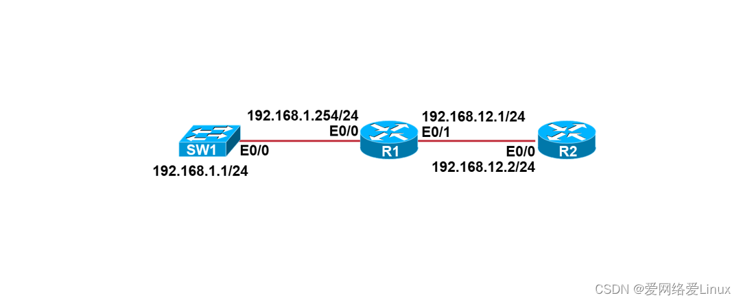
实验需求
- 根据实验拓扑图,完成设备的基本配置;
- 在R1上使用CDP查看SW1和R2的设备信息;
- 注意:CDP默认已经运行,不需要打开。
实验步骤
步骤1:设备的基本配置
配置R1:
Router>enable
Router#configure terminal
Router(config)#hostname R1
R1(config)#no ip domain-lookup
R1(config)#line console 0
R1(config-line)#exec-timeout 0 0
R1(config-line)#logging synchronous
R1(config-line)#exit
R1(config)#interface ethernet0/0
R1(config-if)#ip address 192.168.1.254 255.255.255.0
R1(config-if)#no shutdown
R1(config-if)#exit
R1(config)#interface ethernet0/1
R1(config-if)#ip address 192.168.12.1 255.255.255.0
R1(config-if)#no shutdown
R1(config-if)#end
R1#
配置R2:
Router>enable
Router#configure terminal
Router(config)#hostname R2
R2(config)#no ip domain-lookup
R2(config)#line console 0
R2(config-line)#exec-timeout 0 0
R2(config-line)#logging synchronous
R2(config-line)#exit
R2(config)#interface ethernet0/0
R2(config-if)#ip address 192.168.12.2 255.255.255.0
R2(config-if)#no shutdown
R2(config-if)#end
R2#
配置SW1:
Switch>enable
Switch#configure terminal
Switch(config)#hostname SW1
SW1(config)#no ip domain-lookup
SW1(config)#line console 0
SW1(config-line)#exec-timeout 0 0
SW1(config-line)#logging synchronous
SW1(config-line)#exit
SW1(config)#interface vlan 1
SW1(config-if)#ip address 192.168.1.1 255.255.255.0
SW1(config-if)#no shutdown
SW1(config-if)#exit
SW1(config)#ip default-gateway 192.168.1.254
SW1(config)#end
SW1#
实验检查
步骤1:检查设备的接口状态
检查R1:
R1#show ip interface brief
Interface IP-Address OK? Method Status Protocol
Ethernet0/0 192.168.1.254 YES manual up up
Ethernet0/1 192.168.12.1 YES manual up up
Ethernet0/2 unassigned YES unset administratively down down
Ethernet0/3 unassigned YES unset administratively down down
R1使用到的接口已经配置好IP地址,并且是up up状态。
检查R2:
R2#show ip interface brief
Interface IP-Address OK? Method Status Protocol
Ethernet0/0 192.168.12.2 YES manual up up
Ethernet0/1 unassigned YES TFTP administratively down down
Ethernet0/2 unassigned YES unset administratively down down
Ethernet0/3 unassigned YES unset administratively down down
R2使用到的接口已经配置好IP地址,并且是up up状态。
检查SW1:
SW1#show ip interface brief
Interface IP-Address OK? Method Status Protocol
Ethernet0/0 unassigned YES unset up up
Ethernet0/1 unassigned YES unset up up
Ethernet0/2 unassigned YES unset up up
Ethernet0/3 unassigned YES unset up up
Vlan1 192.168.1.1 YES manual up up
SW1使用到的接口已经配置好IP地址,并且是up up状态。
步骤2:使用CDP查看物理相连的设备信息
检查R1上运行CDP的接口:
R1#show cdp interface
Ethernet0/0 is up, line protocol is up
Encapsulation ARPA
Sending CDP packets every 60 seconds //CDP报文每60秒发送一次
Holdtime is 180 seconds //CDP保持时间是180秒
Ethernet0/1 is up, line protocol is up
Encapsulation ARPA
Sending CDP packets every 60 seconds
Holdtime is 180 seconds
Ethernet0/2 is administratively down, line protocol is down
Encapsulation ARPA
Sending CDP packets every 60 seconds
Holdtime is 180 seconds
Ethernet0/3 is administratively down, line protocol is down
Encapsulation ARPA
Sending CDP packets every 60 seconds
Holdtime is 180 seconds
cdp enabled interfaces : 4
interfaces up : 2
interfaces down : 2
R1的E0/0和E0/1接口已经运行CDP。
检查R1上的CDP邻居:
R1#show cdp neighbors
Capability Codes: R - Router, T - Trans Bridge, B - Source Route Bridge
S - Switch, H - Host, I - IGMP, r - Repeater, P - Phone,
D - Remote, C - CVTA, M - Two-port Mac Relay
Device ID Local Intrfce Holdtme Capability Platform Port ID
SW1 Eth 0/0 169 R S I Linux Uni Eth 0/0
R2 Eth 0/1 163 R B Linux Uni Eth 0/0
Total cdp entries displayed : 2
R1上能够看到SW1和R2两个CDP邻居。
检查R1上的CDP条目:
R1#show cdp entry *
-------------------------
Device ID: SW1 //R1的CDP邻居SW1
Entry address(es):
IP address: 192.168.1.1 //SW1的IP地址
Platform: Linux Unix, Capabilities: Router Switch IGMP
Interface: Ethernet0/0, Port ID (outgoing port): Ethernet0/0 //R1的E0/0连接到了SW1的E0/0
Holdtime : 132 sec
Version :
Cisco IOS Software, Linux Software (I86BI_LINUXL2-ADVENTERPRISEK9-M), Version 15.2(CML_NIGHTLY_20190423)FLO_DSGS7, EARLY DEPLOYMENT DEVELOPMENT BUILD, synced to V152_6_0_81_E
Technical Support: http://www.cisco.com/techsupport
Copyright (c) 1986-2019 by Cisco Systems, Inc.
Compiled Tue 23-Apr-19 02:38 by mmen
advertisement version: 2
VTP Management Domain: ''
Native VLAN: 1
Duplex: full
Management address(es):
IP address: 192.168.1.1
-------------------------
Device ID: R2 //R1的CDP邻居R2
Entry address(es):
IP address: 192.168.12.2 //R2的IP地址
Platform: Linux Unix, Capabilities: Router Source-Route-Bridge
Interface: Ethernet0/1, Port ID (outgoing port): Ethernet0/0 //R1的E0/1连接到了R2的E0/0
Holdtime : 124 sec
Version :
Cisco IOS Software, Linux Software (I86BI_LINUX-ADVENTERPRISEK9-M), Version 15.7(3)M2, DEVELOPMENT TEST SOFTWARE
Technical Support: http://www.cisco.com/techsupport
Copyright (c) 1986-2018 by Cisco Systems, Inc.
Compiled Wed 28-Mar-18 11:18 by prod_rel_team
advertisement version: 2
Management address(es):
IP address: 192.168.12.2
R1有两个CDP邻居,分别是SW1和R2。
实验04:配置LLDP协议
实验目的
- 了解链路层发现协议LLDP的运行原理
- 掌握链路层发现协议LLDP的配置方法
实验拓扑
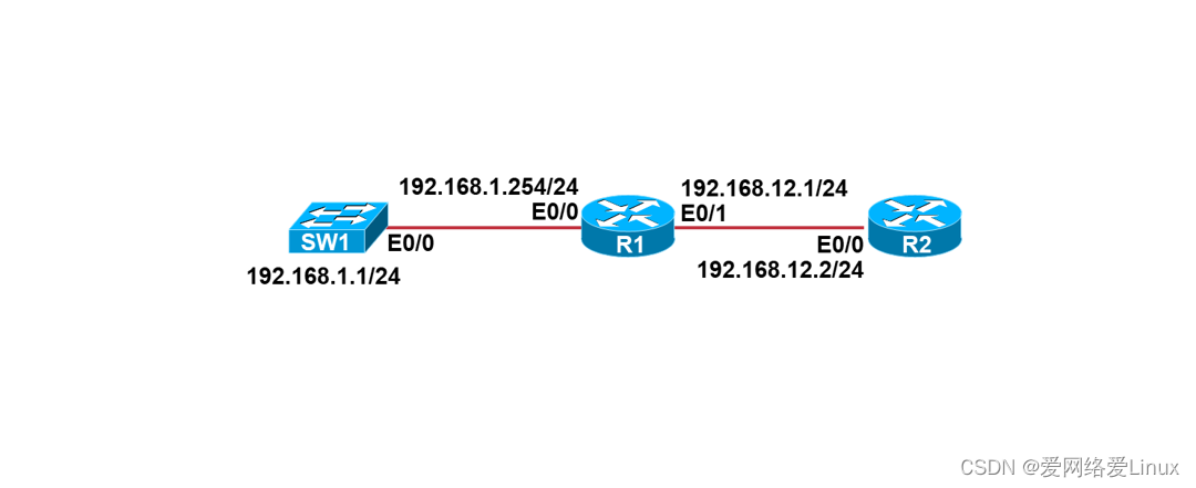
实验需求
- 根据实验拓扑图,完成设备的基本配置;
- 在R1上使用LLDP查看SW1和R2的设备信息;
- 注意:LLDP默认关闭,需要手工打开。
实验步骤
步骤1:设备的基本配置
配置R1:
Router>enable
Router#configure terminal
Router(config)#hostname R1
R1(config)#no ip domain-lookup
R1(config)#line console 0
R1(config-line)#exec-timeout 0 0
R1(config-line)#logging synchronous
R1(config-line)#exit
R1(config)#interface ethernet0/0
R1(config-if)#ip address 192.168.1.254 255.255.255.0
R1(config-if)#no shutdown
R1(config-if)#exit
R1(config)#interface ethernet0/1
R1(config-if)#ip address 192.168.12.1 255.255.255.0
R1(config-if)#no shutdown
R1(config-if)#end
R1#
配置R2:
Router>enable
Router#configure terminal
Router(config)#hostname R2
R2(config)#no ip domain-lookup
R2(config)#line console 0
R2(config-line)#exec-timeout 0 0
R2(config-line)#logging synchronous
R2(config-line)#exit
R2(config)#interface ethernet0/0
R2(config-if)#ip address 192.168.12.2 255.255.255.0
R2(config-if)#no shutdown
R2(config-if)#end
R2#
配置SW1:
Switch>enable
Switch#configure terminal
Switch(config)#hostname SW1
SW1(config)#no ip domain-lookup
SW1(config)#line console 0
SW1(config-line)#exec-timeout 0 0
SW1(config-line)#logging synchronous
SW1(config-line)#exit
SW1(config)#interface vlan 1
SW1(config-if)#ip address 192.168.1.1 255.255.255.0
SW1(config-if)#no shutdown
SW1(config-if)#exit
SW1(config)#ip default-gateway 192.168.1.254
SW1(config)#end
SW1#
步骤2:配置LLDP
配置R1:
R1>enable
R1#configure terminal
R1(config)#lldp run //运行LLDP
配置R2:
R2>enable
R2#configure terminal
R2(config)#lldp run
配置SW1:
SW1>enable
SW1#configure terminal
SW1(config)#lldp run
实验检查
步骤1:检查设备的接口状态
检查R1:
R1#show ip interface brief
Interface IP-Address OK? Method Status Protocol
Ethernet0/0 192.168.1.254 YES manual up up
Ethernet0/1 192.168.12.1 YES manual up up
Ethernet0/2 unassigned YES unset administratively down down
Ethernet0/3 unassigned YES unset administratively down down
R1使用到的接口已经配置好IP地址,并且是up up状态。
检查R2:
R2#show ip interface brief
Interface IP-Address OK? Method Status Protocol
Ethernet0/0 192.168.12.2 YES manual up up
Ethernet0/1 unassigned YES TFTP administratively down down
Ethernet0/2 unassigned YES unset administratively down down
Ethernet0/3 unassigned YES unset administratively down down
R2使用到的接口已经配置好IP地址,并且是up up状态。
检查SW1:
SW1#show ip interface brief
Interface IP-Address OK? Method Status Protocol
Ethernet0/0 unassigned YES unset up up
Ethernet0/1 unassigned YES unset up up
Ethernet0/2 unassigned YES unset up up
Ethernet0/3 unassigned YES unset up up
Vlan1 192.168.1.1 YES manual up up
SW1使用到的接口已经配置好IP地址,并且是up up状态。
步骤2:使用LLDP查看物理相连的设备信息
检查R1上运行LLDP的接口:
R1#show lldp interface
Ethernet0/0:
Tx: enabled
Rx: enabled
Tx state: IDLE
Rx state: WAIT FOR FRAME
Ethernet0/1:
Tx: enabled
Rx: enabled
Tx state: IDLE
Rx state: WAIT FOR FRAME
Ethernet0/2:
Tx: enabled
Rx: enabled
Tx state: INIT
Rx state: WAIT PORT OPER
Ethernet0/3:
Tx: enabled
Rx: enabled
Tx state: INIT
--More--
R1的E0/0和E0/1接口已经运行LLDP。
检查R1上的LLDP邻居:
R1#show lldp neighbors
Capability codes:
(R) Router, (B) Bridge, (T) Telephone, (C) DOCSIS Cable Device
(W) WLAN Access Point, (P) Repeater, (S) Station, (O) Other
Device ID Local Intf Hold-time Capability Port ID
SW1 Et0/0 120 R Et0/0
R2 Et0/1 120 R Et0/0
Total entries displayed: 2
R1上能够看到SW1和R2两个LLDP邻居。
检查R1上的LLDP条目:
R1#show lldp entry *
Capability codes:
(R) Router, (B) Bridge, (T) Telephone, (C) DOCSIS Cable Device
(W) WLAN Access Point, (P) Repeater, (S) Station, (O) Other
------------------------------------------------
Local Intf: Et0/0 //R1本端的接口
Chassis id: aabb.cc00.3000
Port id: Et0/0 //对端的接口
Port Description: Ethernet0/0
System Name: SW1 //对端设备的主机名
System Description:
Cisco IOS Software, Linux Software (I86BI_LINUXL2-ADVENTERPRISEK9-M), Version 15.2(CML_NIGHTLY_20190423)FLO_DSGS7, EARLY DEPLOYMENT DEVELOPMENT BUILD, synced to V152_6_0_81_E
Technical Support: http://www.cisco.com/techsupport
Copyright (c) 1986-2019 by
Time remaining: 103 seconds
System Capabilities: B,R
Enabled Capabilities: R
Management Addresses:
IP: 192.168.1.1 //SW1的IP地址
Auto Negotiation - not supported
Physical media capabilities - not advertised
Media Attachment Unit type - not advertised
Vlan ID: - not advertised
------------------------------------------------
Local Intf: Et0/1
Chassis id: aabb.cc00.2000
Port id: Et0/0
Port Description: Ethernet0/0
System Name: R2
System Description:
Cisco IOS Software, Linux Software (I86BI_LINUX-ADVENTERPRISEK9-M), Version 15.7(3)M2, DEVELOPMENT TEST SOFTWARE
Technical Support: http://www.cisco.com/techsupport
Copyright (c) 1986-2018 by Cisco Systems, Inc.
Compiled Wed 28-Mar-18 11:18 by prod_rel_te
Time remaining: 98 seconds
System Capabilities: B,R
Enabled Capabilities: R
Management Addresses:
IP: 192.168.12.2
Auto Negotiation - not supported
Physical media capabilities - not advertised
Media Attachment Unit type - not advertised
Vlan ID: - not advertised
Total entries displayed: 2
R1有两个CDP邻居,分别是SW1和R2。
实验05:管理交换机MAC地址表
实验目的
- 理解交换机的工作原理
- 掌握交换机MAC地址表的管理方法
实验拓扑
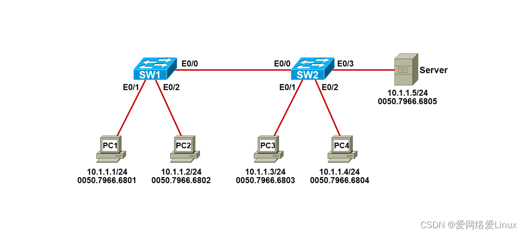
实验需求
- 根据实验拓扑图,完成设备的基本配置;
- 测试主机之间以及主机和服务器之间的网络连通性;
- 把服务器的MAC地址绑定到SW2的MAC地址表。
实验步骤
步骤1:设备的基本配置
配置PC1:
VPCS> set pcname PC1 //设置主机名
PC1> ip 10.1.1.1/24 //设置IP地址
配置PC2:
VPCS> set pcname PC2
PC2> ip 10.1.1.2/24
配置PC3:
VPCS> set pcname PC3
PC3> ip 10.1.1.3/24
配置PC4:
VPCS> set pcname PC4
PC4> ip 10.1.1.4/24
配置Server:
VPCS> set pcname Server
Server> ip 10.1.1.5/24
配置SW1:
Switch>enable
Switch#configure terminal
Switch(config)#hostname SW1
SW1(config)#no ip domain-lookup
SW1(config)#line console 0
SW1(config-line)#exec-timeout 0 0
SW1(config-line)#logging synchronous
SW1(config-line)#end
SW1#
配置SW2:
Switch>enable
Switch#configure terminal
Switch(config)#hostname SW2
SW2(config)#no ip domain-lookup
SW2(config)#line console 0
SW2(config-line)#exec-timeout 0 0
SW2(config-line)#logging synchronous
SW2(config-line)#end
SW2#
步骤2:绑定服务器的MAC地址到SW2的MAC地址表
配置SW2:
SW2#configure terminal
SW2(config)# mac address-table static 0050.7966.6805 vlan 1 interface Ethernet0/3
实验检查
步骤1:网络连通性测试
PC1> ping 10.1.1.2
84 bytes from 10.1.1.2 icmp_seq=1 ttl=64 time=0.502 ms
84 bytes from 10.1.1.2 icmp_seq=2 ttl=64 time=0.738 ms
84 bytes from 10.1.1.2 icmp_seq=3 ttl=64 time=0.584 ms
84 bytes from 10.1.1.2 icmp_seq=4 ttl=64 time=0.646 ms
84 bytes from 10.1.1.2 icmp_seq=5 ttl=64 time=0.730 ms
PC1与PC2的连通性正常。
PC1> ping 10.1.1.3
84 bytes from 10.1.1.3 icmp_seq=1 ttl=64 time=0.968 ms
84 bytes from 10.1.1.3 icmp_seq=2 ttl=64 time=0.816 ms
84 bytes from 10.1.1.3 icmp_seq=3 ttl=64 time=1.265 ms
84 bytes from 10.1.1.3 icmp_seq=4 ttl=64 time=1.122 ms
84 bytes from 10.1.1.3 icmp_seq=5 ttl=64 time=1.242 ms
PC1与PC3的连通性正常。
PC1> ping 10.1.1.4
84 bytes from 10.1.1.4 icmp_seq=1 ttl=64 time=0.900 ms
84 bytes from 10.1.1.4 icmp_seq=2 ttl=64 time=1.303 ms
84 bytes from 10.1.1.4 icmp_seq=3 ttl=64 time=0.880 ms
84 bytes from 10.1.1.4 icmp_seq=4 ttl=64 time=1.086 ms
84 bytes from 10.1.1.4 icmp_seq=5 ttl=64 time=1.259 ms
PC1与PC4的连通性正常。
PC1> ping 10.1.1.5
84 bytes from 10.1.1.5 icmp_seq=1 ttl=64 time=0.875 ms
84 bytes from 10.1.1.5 icmp_seq=2 ttl=64 time=1.248 ms
84 bytes from 10.1.1.5 icmp_seq=3 ttl=64 time=1.145 ms
84 bytes from 10.1.1.5 icmp_seq=4 ttl=64 time=0.942 ms
84 bytes from 10.1.1.5 icmp_seq=5 ttl=64 time=1.317 ms
PC1与Server的连通性正常。
步骤2:管理交换机的MAC地址表
查看SW1的MAC地址表:
SW1#show mac address-table
Mac Address Table
-------------------------------------------
Vlan Mac Address Type Ports
---- ----------- -------- -----
1 0050.7966.6801 DYNAMIC Et0/1
1 0050.7966.6802 DYNAMIC Et0/2
1 0050.7966.6803 DYNAMIC Et0/0
1 0050.7966.6804 DYNAMIC Et0/0
1 0050.7966.6805 DYNAMIC Et0/0
1 aabb.cc00.7000 DYNAMIC Et0/0
Total Mac Addresses for this criterion: 6
SW1已经学习到PC1、PC2、PC3、PC4以及Server的MAC地址,学习方式是Dynamic。
清除SW1动态学习到的MAC地址条目:
SW1#clear mac address-table dynamic
SW1#show mac address-table
Mac Address Table
-------------------------------------------
Vlan Mac Address Type Ports
---- ----------- -------- -----
1 aabb.cc00.7000 DYNAMIC Et0/0
Total Mac Addresses for this criterion: 1
Clear mac address-table dynamic命令能够清除通过Dynamic方式学习到的MAC地址条目。
查看SW2的MAC地址表:
SW2#show mac address-table
Mac Address Table
-------------------------------------------
Vlan Mac Address Type Ports
---- ----------- -------- -----
1 0050.7966.6801 DYNAMIC Et0/0
1 0050.7966.6803 DYNAMIC Et0/1
1 0050.7966.6804 DYNAMIC Et0/2
1 0050.7966.6805 STATIC Et0/3
1 aabb.cc00.6000 DYNAMIC Et0/0
Total Mac Addresses for this criterion: 5
Server的MAC地址是静态绑定的,所以类型是STATIC。
清除SW2动态学习到的MAC地址条目:
SW2#clear mac address-table dynamic
SW2#show mac address-table
Mac Address Table
-------------------------------------------
Vlan Mac Address Type Ports
---- ----------- -------- -----
1 0050.7966.6805 STATIC Et0/3
1 aabb.cc00.6000 DYNAMIC Et0/0
Total Mac Addresses for this criterion: 2
Clear mac address-table dynamic命令无法清除静态绑定的MAC地址条目。
实验06:配置VLAN
实验目的
- 理解VLAN的运行原理
- 掌握VLAN的配置方法
实验拓扑
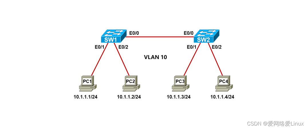
实验需求
- 根据实验拓扑图,完成设备的基本配置;
- 分别在SW1和SW2上创建VLAN 10,名字为IT;
- 分别在SW1和SW2上把接口E0/0、E0/1和E0/2划入VLAN10;
- 测试PC之间的网络连通性。
实验步骤
步骤1:设备的基本配置
配置PC1:
VPCS> set pcname PC1 //设置主机名
PC1> ip 10.1.1.1/24 //设置IP地址
配置PC2:
VPCS> set pcname PC2
PC2> ip 10.1.1.2/24
配置PC3:
VPCS> set pcname PC3
PC3> ip 10.1.1.3/24
配置PC4:
VPCS> set pcname PC4
PC4> ip 10.1.1.4/24
配置SW1:
Switch>enable
Switch#configure terminal
Switch(config)#hostname SW1
SW1(config)#no ip domain-lookup
SW1(config)#line console 0
SW1(config-line)#exec-timeout 0 0
SW1(config-line)#logging synchronous
SW1(config-line)#end
SW1#
配置SW2:
Switch>enable
Switch#configure terminal
Switch(config)#hostname SW2
SW2(config)#no ip domain-lookup
SW2(config)#line console 0
SW2(config-line)#exec-timeout 0 0
SW2(config-line)#logging synchronous
SW2(config-line)#end
SW2#
步骤2:VLAN的配置
配置SW1:
SW1(config)#vlan 10
SW1(config-vlan)#name IT
SW1(config-vlan)#exit
SW1(config)#interface Eth0/0
SW1(config-if)#switchport mode access
SW1(config-if)#switchport access vlan 10
SW1(config-if)#exit
SW1(config)#interface Eth0/1
SW1(config-if)#switchport mode access
SW1(config-if)#switchport access vlan 10
SW1(config-if)#exit
SW1(config)#interface Eth0/2
SW1(config-if)#switchport mode access
SW1(config-if)#switchport access vlan 10
SW1(config-if)#end
SW1#
配置SW2:
SW2(config)#vlan 10
SW2(config-vlan)#name IT
SW2(config-vlan)#exit
SW2(config)#interface range Eth0/0 - 2 //同时将多个端口划入VLAN 10
SW2(config-if-range)#switchport mode access
SW2(config-if-range)#switchport access vlan 10
SW2(config-if-range)#end
SW2#
实验检查
步骤1:检查SW1的VLAN信息
SW1#show vlan brief
VLAN Name Status Ports
---- -------------------------------- --------- -------------------------------
1 default active Et0/3
10 IT active Et0/0, Et0/1, Et0/2
1002 fddi-default act/unsup
1003 token-ring-default act/unsup
1004 fddinet-default act/unsup
1005 trnet-default act/unsup
VLAN10有三个接口,分别是Et0/0、Et0/1、Et0/2。
步骤2:检查SW1的接口配置
SW1#sh run int Eth0/0
Building configuration...
Current configuration : 80 bytes
!
interface Ethernet0/0
switchport access vlan 10
switchport mode access
end
SW1#sh run int Eth0/1
Building configuration...
Current configuration : 80 bytes
!
interface Ethernet0/1
switchport access vlan 10
switchport mode access
end
SW1#sh run int Eth0/2
Building configuration...
Current configuration : 80 bytes
!
interface Ethernet0/2
switchport access vlan 10
switchport mode access
end
步骤3:测试网络的连通性
PC1> ping 10.1.1.2
84 bytes from 10.1.1.2 icmp_seq=1 ttl=64 time=0.835 ms
84 bytes from 10.1.1.2 icmp_seq=2 ttl=64 time=0.765 ms
84 bytes from 10.1.1.2 icmp_seq=3 ttl=64 time=0.866 ms
84 bytes from 10.1.1.2 icmp_seq=4 ttl=64 time=0.824 ms
84 bytes from 10.1.1.2 icmp_seq=5 ttl=64 time=0.828 ms
PC1与PC2的连通性正常。
PC1> ping 10.1.1.3
84 bytes from 10.1.1.3 icmp_seq=1 ttl=64 time=1.105 ms
84 bytes from 10.1.1.3 icmp_seq=2 ttl=64 time=1.337 ms
84 bytes from 10.1.1.3 icmp_seq=3 ttl=64 time=1.235 ms
84 bytes from 10.1.1.3 icmp_seq=4 ttl=64 time=1.291 ms
84 bytes from 10.1.1.3 icmp_seq=5 ttl=64 time=1.059 ms
PC1与PC3的连通性正常。
PC1> ping 10.1.1.4
84 bytes from 10.1.1.4 icmp_seq=1 ttl=64 time=0.826 ms
84 bytes from 10.1.1.4 icmp_seq=2 ttl=64 time=0.957 ms
84 bytes from 10.1.1.4 icmp_seq=3 ttl=64 time=1.194 ms
84 bytes from 10.1.1.4 icmp_seq=4 ttl=64 time=1.214 ms
84 bytes from 10.1.1.4 icmp_seq=5 ttl=64 time=1.184 ms
PC1与PC4的连通性正常。
实验07:配置Trunk
实验目的
- 理解Trunk的运行原理
- 掌握Trunk的配置方法
实验拓扑
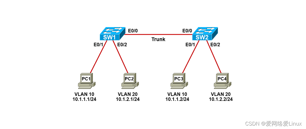
实验需求
- 根据实验拓扑图,完成设备的基本配置;
- 分别在SW1和SW2创建VLAN10和VLAN20,名字为IT和HR;
- 分别在SW1和SW2上把相应的接口划入VLAN10和VLAN20;
- 把SW1和SW2互连的链路配置成Trunk,采用Dot1q封装;
- 测试PC之间的网络连通性。
- 实验步骤
步骤1:设备的基本配置
配置PC1:
VPCS> set pcname PC1 //设置主机名
PC1> ip 10.1.1.1/24 //设置IP地址
配置PC2:
VPCS> set pcname PC2
PC2> ip 10.1.2.1/24
配置PC3:
VPCS> set pcname PC3
PC3> ip 10.1.1.2/24
配置PC4:
VPCS> set pcname PC4
PC4> ip 10.1.2.2/24
配置SW1:
Switch>enable
Switch#configure terminal
Switch(config)#hostname SW1
SW1(config)#no ip domain-lookup
SW1(config)#line console 0
SW1(config-line)#exec-timeout 0 0
SW1(config-line)#logging synchronous
SW1(config-line)#end
SW1#
配置SW2:
Switch>enable
Switch#configure terminal
Switch(config)#hostname SW2
SW2(config)#no ip domain-lookup
SW2(config)#line console 0
SW2(config-line)#exec-timeout 0 0
SW2(config-line)#logging synchronous
SW2(config-line)#end
SW2#
步骤2:VLAN的配置
配置SW1:
SW1(config)#vlan 10
SW1(config-vlan)#name IT
SW1(config-vlan)#exit
SW1(config)#vlan 20
SW1(config-vlan)#name HR
SW1(config-vlan)#exit
SW1(config)#interface Eth0/1
SW1(config-if)#switchport mode access
SW1(config-if)#switchport access vlan 10
SW1(config-if)#exit
SW1(config)#interface Eth0/2
SW1(config-if)#switchport mode access
SW1(config-if)#switchport access vlan 20
SW1(config-if)#end
SW1#
配置SW2:
SW2(config)#vlan 10
SW2(config-vlan)#name IT
SW2(config-vlan)#exit
SW2(config)#vlan 20
SW2(config-vlan)#name HR
SW2(config-vlan)#exit
SW2(config)#interface Eth0/1
SW2(config-if)#switchport mode access
SW2(config-if)#switchport access vlan 10
SW2(config-if)#exit
SW2(config)#interface Eth0/2
SW2(config-if)#switchport mode access
SW2(config-if)#switchport access vlan 20
SW2(config-if)#end
SW2#
步骤3:Trunk的配置
配置SW1:
SW1(config)#interface Eth0/0
SW1(config-if)#switchport trunk encapsulation dot1q
SW1(config-if)#switchport mode trunk
SW1(config-if)#end
SW1#
配置SW2:
SW2(config)#interface Eth0/0
SW2(config-if)#switchport trunk encapsulation dot1q
SW2(config-if)#switchport mode trunk
SW2(config-if)#end
SW2#
实验检查
步骤1:检查VLAN
检查SW1:
SW1#show vlan brief
VLAN Name Status Ports
---- -------------------------------- --------- -------------------------------
1 default active Et0/3
10 IT active Et0/1
20 HR active Et0/2
1002 fddi-default act/unsup
1003 token-ring-default act/unsup
1004 fddinet-default act/unsup
1005 trnet-default act/unsup
SW1已经创建好VLAN10和VLAN20,并已将对应接口划入。
检查SW2:
SW2#show vlan brief
VLAN Name Status Ports
---- -------------------------------- --------- -------------------------------
1 default active Et0/3
10 IT active Et0/1
20 HR active Et0/2
1002 fddi-default act/unsup
1003 token-ring-default act/unsup
1004 fddinet-default act/unsup
1005 trnet-default act/unsup
SW2已经创建好VLAN10和VLAN20,并已将对应接口划入。
步骤2:检查Trunk
检查SW1:
SW1#show interfaces Eth0/0 switchport
Name: Et0/0
Switchport: Enabled
Administrative Mode: trunk
Operational Mode: trunk
Administrative Trunking Encapsulation: dot1q
Operational Trunking Encapsulation: dot1q
Negotiation of Trunking: On
Access Mode VLAN: 1 (default)
Trunking Native Mode VLAN: 1 (default)
Administrative Native VLAN tagging: enabled
Voice VLAN: none
Administrative private-vlan host-association: none
Administrative private-vlan mapping: none
Administrative private-vlan trunk native VLAN: none
Administrative private-vlan trunk Native VLAN tagging: enabled
Administrative private-vlan trunk encapsulation: dot1q
Administrative private-vlan trunk normal VLANs: none
Administrative private-vlan trunk associations: none
Administrative private-vlan trunk mappings: none
Operational private-vlan: none
Trunking VLANs Enabled: ALL
Pruning VLANs Enabled: 2-1001
Capture Mode Disabled
Capture VLANs Allowed: ALL
Protected: false
Appliance trust: none
E0/0接口当前是Trunk,封装的协议是dot1q。
SW1#show interfaces trunk
Port Mode Encapsulation Status Native vlan
Et0/0 on 802.1q trunking 1
Port Vlans allowed on trunk
Et0/0 1-4094
Port Vlans allowed and active in management domain
Et0/0 1,10,20
Port Vlans in spanning tree forwarding state and not pruned
Et0/0 1,10,20
E0/0封装的Trunk协议是dot1q,当前的状态是trunking。
SW1#sh run int Eth0/0
Building configuration...
Current configuration : 90 bytes
!
interface Ethernet0/0
switchport trunk encapsulation dot1q
switchport mode trunk
end
E0/0接口的Trunk封装协议是dot1q,模式是trunk。
检查SW2:
SW2#show interfaces trunk
Port Mode Encapsulation Status Native vlan
Et0/0 on 802.1q trunking 1
Port Vlans allowed on trunk
Et0/0 1-4094
Port Vlans allowed and active in management domain
Et0/0 1,10,20
Port Vlans in spanning tree forwarding state and not pruned
Et0/0 1,10,20
E0/0封装的Trunk协议是dot1q,当前的状态是trunking。
步骤4:网络连通性测试
测试PC1和PC3的连通性:
PC1> ping 10.1.1.2
84 bytes from 10.1.1.2 icmp_seq=1 ttl=64 time=1.603 ms
84 bytes from 10.1.1.2 icmp_seq=2 ttl=64 time=1.234 ms
84 bytes from 10.1.1.2 icmp_seq=3 ttl=64 time=1.027 ms
84 bytes from 10.1.1.2 icmp_seq=4 ttl=64 time=2.372 ms
84 bytes from 10.1.1.2 icmp_seq=5 ttl=64 time=1.200 ms
PC1和PC3的网络连通性正常。
测试PC2和PC4的连通性:
PC2> ping 10.1.2.2
84 bytes from 10.1.2.2 icmp_seq=1 ttl=64 time=0.887 ms
84 bytes from 10.1.2.2 icmp_seq=2 ttl=64 time=0.932 ms
84 bytes from 10.1.2.2 icmp_seq=3 ttl=64 time=1.295 ms
84 bytes from 10.1.2.2 icmp_seq=4 ttl=64 time=0.926 ms
84 bytes from 10.1.2.2 icmp_seq=5 ttl=64 time=1.011 ms
PC2和PC4的网络连通性正常。
实验08:配置VTP
实验目的
- 了解VTP的运行原理
- 掌握VTP的配置方法
实验拓扑
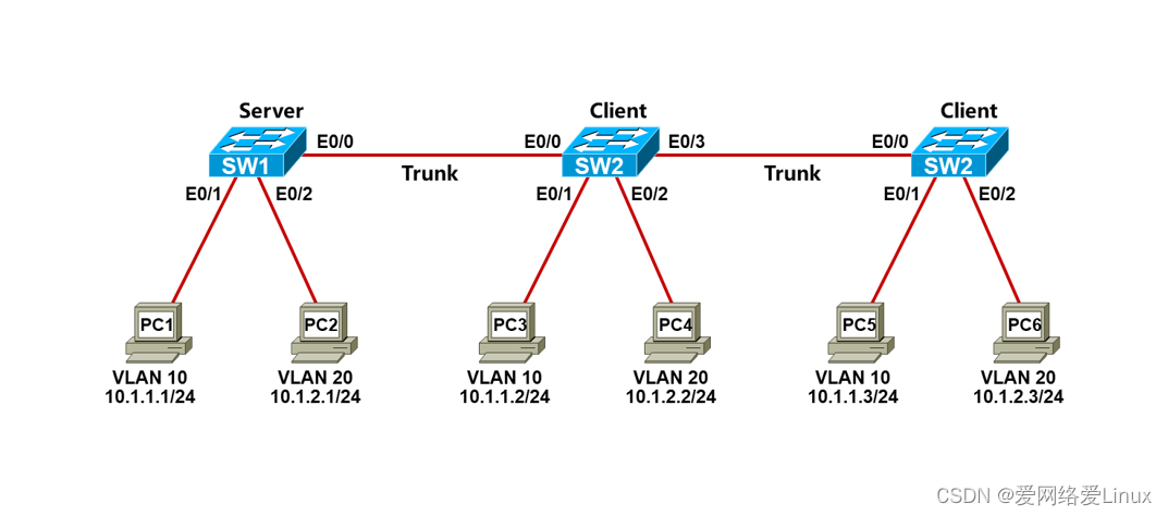
实验需求
- 根据实验拓扑图,完成设备的基本配置;
- 把交换机互连的链路配置成Trunk,采用Dot1q封装;
- SW1是VTP服务器,SW2和SW3是VTP客户端,VTP域名为xmws,VTP密码为wisdom,开启VTP裁剪;
- 在SW1上创建VLAN10和VLAN20,名字为IT和HR;
- 分别在SW1、SW2和SW3上把相应的接口划入VLAN10和VLAN20;
实验步骤
步骤1:设备的基本配置
配置PC1:
VPCS> set pcname PC1 //设置主机名
PC1> ip 10.1.1.1/24 //设置IP地址
配置PC2:
VPCS> set pcname PC2
PC2> ip 10.1.2.1/24
配置PC3:
VPCS> set pcname PC3
PC3> ip 10.1.1.2/24
配置PC4:
VPCS> set pcname PC4
PC4> ip 10.1.2.2/24
配置PC5:
VPCS> set pcname PC5
PC5> ip 10.1.1.3/24
配置PC6:
VPCS> set pcname PC6
PC6> ip 10.1.2.3/24
配置SW1:
Switch>enable
Switch#configure terminal
Switch(config)#hostname SW1
SW1(config)#no ip domain-lookup
SW1(config)#line console 0
SW1(config-line)#exec-timeout 0 0
SW1(config-line)#logging synchronous
SW1(config-line)#end
SW1#
配置SW2:
Switch>enable
Switch#configure terminal
Switch(config)#hostname SW2
SW2(config)#no ip domain-lookup
SW2(config)#line console 0
SW2(config-line)#exec-timeout 0 0
SW2(config-line)#logging synchronous
SW2(config-line)#end
SW2#
配置SW3:
Switch>enable
Switch#configure terminal
Switch(config)#hostname SW3
SW3(config)#no ip domain-lookup
SW3(config)#line console 0
SW3(config-line)#exec-timeout 0 0
SW3(config-line)#logging synchronous
SW3(config-line)#end
SW3#
步骤2:配置Trunk
配置SW1:
SW1(config)#interface Eth0/0
SW1(config-if)#switchport trunk encapsulation dot1q
SW1(config-if)#switchport mode trunk
SW1(config-if)#end
SW1#
配置SW2:
SW2(config)#interface range Eth0/0 , Eth0/3
SW2(config-if-range)#switchport trunk encapsulation dot1q
SW2(config-if-range)#switchport mode trunk
SW2(config-if-range)#end
SW2#
配置SW3:
SW3(config)#interface Eth0/0
SW3(config-if)#switchport trunk encapsulation dot1q
SW3(config-if)#switchport mode trunk
SW3(config-if)#end
SW3#
步骤3:配置VTP
配置SW1:
SW1(config)#vtp mode server
SW1(config)#vtp domain xmws
SW1(config)#vtp password wisdom
SW1(config)#vtp pruning
配置SW2:
SW2(config)#vtp mode client
SW2(config)#vtp domain xmws
SW2(config)#vtp password wisdom
配置SW3:
SW3(config)#vtp mode client
SW3(config)#vtp domain xmws
SW3(config)#vtp password wisdom
步骤4:配置VLAN
配置SW1:
SW1(config)#vlan 10
SW1(config-vlan)#name IT
SW1(config-vlan)#exit
SW1(config)#vlan 20
SW1(config-vlan)#name HR
SW1(config-vlan)#exit
SW1(config)#interface Eth0/1
SW1(config-if)#switchport mode access
SW1(config-if)#switchport access vlan 10
SW1(config-if)#exit
SW1(config)#interface Eth0/2
SW1(config-if)#switchport mode access
SW1(config-if)#switchport access vlan 20
SW1(config-if)#end
SW1#
配置SW2:
SW2(config)#interface Eth0/1
SW2(config-if)#switchport mode access
SW2(config-if)#switchport access vlan 10
SW2(config-if)#exit
SW2(config)#interface Eth0/2
SW2(config-if)#switchport mode access
SW2(config-if)#switchport access vlan 20
SW2(config-if)#end
SW2#
配置SW3:
SW3(config)#interface Eth0/1
SW3(config-if)#switchport mode access
SW3(config-if)#switchport access vlan 10
SW3(config-if)#exit
SW3(config)#interface Eth0/2
SW3(config-if)#switchport mode access
SW3(config-if)#switchport access vlan 20
SW3(config-if)#end
SW3#
实验检查
步骤1:检查VTP
检查SW1:
SW1#show vtp status
VTP Version capable : 1 to 3
VTP version running : 1
VTP Domain Name : xmws
VTP Pruning Mode : Enabled
VTP Traps Generation : Disabled
Device ID : aabb.cc80.7000
Configuration last modified by 0.0.0.0 at 4-23-20 17:18:33
Local updater ID is 0.0.0.0 (no valid interface found)
Feature VLAN:
--------------
VTP Operating Mode : Server
Maximum VLANs supported locally : 1005
Number of existing VLANs : 7
Configuration Revision : 3
MD5 digest : 0x85 0x2D 0x06 0xA3 0x42 0x1B 0x93 0xEE
0x90 0x66 0x1F 0x3C 0xA9 0x52 0xD5 0x38
SW1是VTP服务器,域名是xmws,裁剪已经启用。
SW1#show vtp password
VTP Password: wisdom
VTP密码是wisdom。
检查SW2:
SW2#show vtp status
VTP Version capable : 1 to 3
VTP version running : 1
VTP Domain Name : xmws
VTP Pruning Mode : Enabled
VTP Traps Generation : Disabled
Device ID : aabb.cc80.8000
Configuration last modified by 0.0.0.0 at 4-23-20 17:18:33
Feature VLAN:
--------------
VTP Operating Mode : Client
Maximum VLANs supported locally : 1005
Number of existing VLANs : 7
Configuration Revision : 3
MD5 digest : 0x85 0x2D 0x06 0xA3 0x42 0x1B 0x93 0xEE
0x90 0x66 0x1F 0x3C 0xA9 0x52 0xD5 0x38
SW2是VTP客户端,域名是xmws,裁剪已经启用。
SW2#show vtp password
VTP Password: wisdom
VTP密码是wisdom。
步骤2:检查VLAN信息
检查SW1:
SW1#show vlan brief
VLAN Name Status Ports
---- -------------------------------- --------- -------------------------------
1 default active Et0/3
10 IT active Et0/1
20 HR active Et0/2
1002 fddi-default act/unsup
1003 token-ring-default act/unsup
1004 fddinet-default act/unsup
1005 trnet-default act/unsup
SW1作为VTP服务器,已经创建好VLAN10和VLAN20。
检查SW2:
SW2#show vlan brief
VLAN Name Status Ports
---- -------------------------------- --------- -------------------------------
1 default active
10 IT active Et0/1
20 HR active Et0/2
1002 fddi-default act/unsup
1003 token-ring-default act/unsup
1004 fddinet-default act/unsup
1005 trnet-default act/unsup
SW2作为VTP客户端,已经同步VTP服务器的VLAN信息。
检查SW3:
SW3#show vlan brief
VLAN Name Status Ports
---- -------------------------------- --------- -------------------------------
1 default active Et0/3
10 IT active Et0/1
20 HR active Et0/2
1002 fddi-default act/unsup
1003 token-ring-default act/unsup
1004 fddinet-default act/unsup
1005 trnet-default act/unsup
SW3作为VTP客户端,已经同步VTP服务器的VLAN信息。
实验09:配置生成树
实验目的
- 理解生成树的运行原理
- 掌握生成树的配置方法
实验拓扑
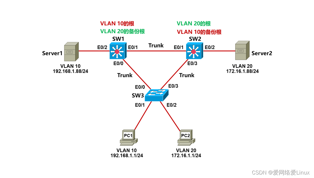
实验需求
- 根据实验拓扑图,完成设备的基本配置;
- 把交换机互连的链路配置成Trunk,采用Dot1q封装;
- 分别在SW1、SW2和SW3上创建VLAN10和VLAN20,并将相应的接口划到对应的VLAN;
- SW1要作为VLAN10的根,VLAN20的备份根,使PC1访问Server1的路径通过:PC1->SW3->SW1->Server1;
- SW2要作为VLAN20的根,VLAN10的备份根,使PC2访问Server2的路径通过:PC2->SW3->SW2->Server2;
实验步骤
步骤1:设备的基本配置
配置PC1:
VPCS> set pcname PC1 //设置主机名
PC1> ip 192.168.1.1/24 //设置IP地址
配置PC2:
VPCS> set pcname PC2
PC2> ip 172.16.1.1/24
配置Server1:
VPCS> set pcname Server1
Server1> ip 192.168.1.88/24
配置Server2:
VPCS> set pcname Server2
Server2> ip 172.16.1.88/24
配置SW1:
Switch>enable
Switch#configure terminal
Switch(config)#hostname SW1
SW1(config)#no ip domain-lookup
SW1(config)#line console 0
SW1(config-line)#exec-timeout 0 0
SW1(config-line)#logging synchronous
SW1(config-line)#end
SW1#
配置SW2:
Switch>enable
Switch#configure terminal
Switch(config)#hostname SW2
SW2(config)#no ip domain-lookup
SW2(config)#line console 0
SW2(config-line)#exec-timeout 0 0
SW2(config-line)#logging synchronous
SW2(config-line)#end
SW2#
配置SW3:
Switch>enable
Switch#configure terminal
Switch(config)#hostname SW3
SW3(config)#no ip domain-lookup
SW3(config)#line console 0
SW3(config-line)#exec-timeout 0 0
SW3(config-line)#logging synchronous
SW3(config-line)#end
SW3#
步骤2:配置Trunk与VLAN
配置SW1:
SW1(config)#interface range Eth0/0 - 1
SW1(config-if-range)#switchport trunk encapsulation dot1q
SW1(config-if-range)#switchport mode trunk
SW1(config-if-range)#exit
SW1(config)#vlan 10
SW1(config-vlan)#name IT
SW1(config-vlan)#exit
SW1(config)#vlan 20
SW1(config-vlan)#name HR
SW1(config-vlan)#exit
SW1(config)#interface Eth0/2
SW1(config-if)#switchport mode access
SW1(config-if)#switchport access vlan 10
SW1(config-if)#exit
SW1(config)#end
SW1#
配置SW2:
SW2(config)#interface range Eth0/1 , Eth0/3
SW2(config-if-range)#switchport trunk encapsulation dot1q
SW2(config-if-range)#switchport mode trunk
SW2(config-if-range)#exit
SW2(config)#vlan 10
SW2(config-vlan)#name IT
SW2(config-vlan)#exit
SW2(config)#vlan 20
SW2(config-vlan)#name HR
SW2(config-vlan)#exit
SW2(config)#interface Eth0/2
SW2(config-if)#switchport mode access
SW2(config-if)#switchport access vlan 20
SW2(config-if)#exit
SW2(config)#end
SW2#
配置SW3:
SW3(config)#interface range Eth0/0 , Eth0/3
SW3(config-if-range)#switchport trunk encapsulation dot1q
SW3(config-if-range)#switchport mode trunk
SW3(config-if-range)#exit
SW3(config)#vlan 10
SW3(config-vlan)#name IT
SW3(config-vlan)#exit
SW3(config)#vlan 20
SW3(config-vlan)#name HR
SW3(config-vlan)#exit
SW3(config)#interface Eth0/1
SW3(config-if)#switchport mode access
SW3(config-if)#switchport access vlan 10
SW3(config-if)#exit
SW3(config)#interface Eth0/2
SW3(config-if)#switchport mode access
SW3(config-if)#switchport access vlan 20
SW2(config-if)#exit
SW3(config)#end
SW3#
步骤3:配置生成树
配置SW1:
SW1(config)#spanning-tree vlan 10 root primary
SW1(config)#spanning-tree vlan 20 root secondary
配置SW2:
SW2(config)#spanning-tree vlan 20 root primary
SW2(config)#spanning-tree vlan 10 root secondary
实验检查
步骤1:检查VLAN10的生成树
检查SW1:
SW1#show spanning-tree vlan 10
VLAN0010
Spanning tree enabled protocol ieee
Root ID Priority 24586
Address aabb.cc00.1000
This bridge is the root
Hello Time 2 sec Max Age 20 sec Forward Delay 15 sec
Bridge ID Priority 24586 (priority 24576 sys-id-ext 10)
Address aabb.cc00.1000
Hello Time 2 sec Max Age 20 sec Forward Delay 15 sec
Aging Time 15 sec
Interface Role Sts Cost Prio.Nbr Type
------------------- ---- --- --------- -------- --------------------------------
Et0/0 Desg FWD 100 128.1 P2p
Et0/1 Desg FWD 100 128.2 P2p
Et0/2 Desg FWD 100 128.3 P2p
SW1是VLAN10的根网桥,因为SW2是VLAN10的备份根网桥,所以SW3的E0/3针对VLAN10肯定是阻塞状态。
检查SW3:
SW3#show spanning-tree vlan 10
VLAN0010
Spanning tree enabled protocol ieee
Root ID Priority 24586
Address aabb.cc00.1000
Cost 100
Port 1 (Ethernet0/0)
Hello Time 2 sec Max Age 20 sec Forward Delay 15 sec
Bridge ID Priority 32778 (priority 32768 sys-id-ext 10)
Address aabb.cc00.3000
Hello Time 2 sec Max Age 20 sec Forward Delay 15 sec
Aging Time 300 sec
Interface Role Sts Cost Prio.Nbr Type
------------------- ---- --- --------- -------- --------------------------------
Et0/0 Root FWD 100 128.1 P2p
Et0/1 Desg FWD 100 128.2 P2p
Et0/3 Altn BLK 100 128.4 P2p
针对VLAN10,SW3的E0/3是阻塞的,E0/0是转发的,这样PC1访问Server1的路径就是:PC1->SW3->SW1->Server1。
步骤2:检查VLAN20的生成树
检查SW2:
SW2#show spanning-tree vlan 20
VLAN0020
Spanning tree enabled protocol ieee
Root ID Priority 24596
Address aabb.cc00.2000
This bridge is the root
Hello Time 2 sec Max Age 20 sec Forward Delay 15 sec
Bridge ID Priority 24596 (priority 24576 sys-id-ext 20)
Address aabb.cc00.2000
Hello Time 2 sec Max Age 20 sec Forward Delay 15 sec
Aging Time 300 sec
Interface Role Sts Cost Prio.Nbr Type
------------------- ---- --- --------- -------- --------------------------------
Et0/1 Desg FWD 100 128.2 P2p
Et0/2 Desg FWD 100 128.3 P2p
Et0/3 Desg FWD 100 128.4 P2p
SW2是VLAN20的根网桥,因为SW1是VLAN10的备份根网桥,所以SW3的E0/0针对VLAN20肯定是阻塞状态。
检查SW3:
SW3#show spanning-tree vlan 20
VLAN0020
Spanning tree enabled protocol ieee
Root ID Priority 24596
Address aabb.cc00.2000
Cost 100
Port 4 (Ethernet0/3)
Hello Time 2 sec Max Age 20 sec Forward Delay 15 sec
Bridge ID Priority 32788 (priority 32768 sys-id-ext 20)
Address aabb.cc00.3000
Hello Time 2 sec Max Age 20 sec Forward Delay 15 sec
Aging Time 300 sec
Interface Role Sts Cost Prio.Nbr Type
------------------- ---- --- --------- -------- --------------------------------
Et0/0 Altn BLK 100 128.1 P2p
Et0/2 Desg FWD 100 128.3 P2p
Et0/3 Root FWD 100 128.4 P2p
针对VLAN20,SW3的E0/0是阻塞的,E0/3是转发的,这样PC2访问Server2的路径就是:PC2->SW3->SW2->Server2。
实验10:配置VLAN间路由_01
实验目的
- 理解VLAN间路由的原理
- 掌握VLAN间路由的配置
实验拓扑

实验需求
- 根据实验拓扑图,完成设备的基本配置;
- 配置单臂路由实现VLAN10和VLAN20之间的互访。
实验步骤
步骤1:设备的基本配置
配置PC1:
VPCS> set pcname PC1 //设置主机名
PC1> ip 192.168.1.1/24 192.168.1.254 //设置IP地址与网关
配置PC2:
VPCS> set pcname PC2
PC2> ip 172.16.1.1/24 172.16.1.254
配置R1:
Router>enable
Router#configure terminal
Router(config)#hostname R1
R1(config)#no ip domain-lookup
R1(config)#line console 0
R1(config-line)#exec-timeout 0 0
R1(config-line)#logging synchronous
R1(config-line)#end
R1#
配置SW1:
Switch>enable
Switch#configure terminal
Switch(config)#hostname SW1
SW1(config)#no ip domain-lookup
SW1(config)#line console 0
SW1(config-line)#exec-timeout 0 0
SW1(config-line)#logging synchronous
SW1(config-line)#end
SW1#
步骤2:单臂路由的配置
配置R1:
R1(config)#interface Ethernet0/0
R1(config-if)#no shutdown
R1(config-if)#exit
R1(config)#interface Ethernet0/0.10
R1(config-if)#encapsulation dot1Q 10
R1(config-if)#ip address 192.168.1.254 255.255.255.0
R1(config-if)#exit
R1(config)#interface Ethernet0/0.20
R1(config-if)#encapsulation dot1Q 20
R1(config-if)#ip address 172.16.1.254 255.255.255.0
R1(config-if)#end
R1#
配置SW1:
SW1(config)#vlan 10
SW1(config-vlan)#name IT
SW1(config-vlan)#exit
SW1(config)#vlan 20
SW1(config-vlan)#name HR
SW1(config-vlan)#exit
SW1(config)#interface Ethernet0/0
SW1(config-if)#switchport trunk encapsulation dot1q
SW1(config-if)#switchport mode trunk
SW1(config)#interface Ethernet0/1
SW1(config-if)#switchport mode access
SW1(config-if)#switchport access vlan 10
SW1(config)#interface Ethernet0/2
SW1(config-if)#switchport mode access
SW1(config-if)#switchport access vlan 20
实验检查
步骤1:检查R1
检查R1的接口状态:
R1#show ip interface brief
Interface IP-Address OK? Method Status Protocol
Ethernet0/0 unassigned YES unset up up
Ethernet0/0.10 192.168.1.254 YES manual up up
Ethernet0/0.20 172.16.1.254 YES manual up up
Ethernet0/1 unassigned YES unset administratively down down
Ethernet0/2 unassigned YES unset administratively down down
Ethernet0/3 unassigned YES unset administratively down down
检查R1的子接口信息:
R1#show vlans
Virtual LAN ID: 1 (IEEE 802.1Q Encapsulation)
vLAN Trunk Interface: Ethernet0/0
This is configured as native Vlan for the following interface(s) :
Ethernet0/0
Protocols Configured: Address: Received: Transmitted:
Ethernet0/0 (1)
Other 0 20
0 packets, 0 bytes input
20 packets, 1440 bytes output
Virtual LAN ID: 10 (IEEE 802.1Q Encapsulation)
vLAN Trunk Interface: Ethernet0/0.10
Protocols Configured: Address: Received: Transmitted:
Ethernet0/0.10 (10)
IP 192.168.1.254 14 9
Other 0 3
72 packets, 5232 bytes input
12 packets, 1056 bytes output
Virtual LAN ID: 20 (IEEE 802.1Q Encapsulation)
vLAN Trunk Interface: Ethernet0/0.20
Protocols Configured: Address: Received: Transmitted:
Ethernet0/0.20 (20)
IP 172.16.1.254 14 9
Other 0 3
72 packets, 5232 bytes input
12 packets, 1056 bytes output
子接口E0/0.10的VLAN ID是10,IP地址是192.168.1.254;
子接口E0/0.20的VLAN ID是20,IP地址是172.16.1.254。
步骤2:检查SW1
检查SW1的VLAN信息:
SW1#show vlan brief
VLAN Name Status Ports
---- -------------------------------- --------- -------------------------------
1 default active Et0/3
10 VLAN0010 active Et0/1
20 VLAN0020 active Et0/2
1002 fddi-default act/unsup
1003 token-ring-default act/unsup
1004 fddinet-default act/unsup
1005 trnet-default act/unsup
检查SW1的Trunk状态:
SW1#show interfaces trunk
Port Mode Encapsulation Status Native vlan
Et0/0 on 802.1q trunking 1
Port Vlans allowed on trunk
Et0/0 1-4094
Port Vlans allowed and active in management domain
Et0/0 1,10,20
Port Vlans in spanning tree forwarding state and not pruned
Et0/0 1,10,20
步骤3:测试网络连通性
PC1访问PC2:
PC1> ping 172.16.1.1
84 bytes from 172.16.1.1 icmp_seq=1 ttl=63 time=1.597 ms
84 bytes from 172.16.1.1 icmp_seq=2 ttl=63 time=1.237 ms
84 bytes from 172.16.1.1 icmp_seq=3 ttl=63 time=1.975 ms
84 bytes from 172.16.1.1 icmp_seq=4 ttl=63 time=1.274 ms
84 bytes from 172.16.1.1 icmp_seq=5 ttl=63 time=1.243 ms
PC1> trace 172.16.1.1
trace to 172.16.1.1, 8 hops max, press Ctrl+C to stop
1 192.168.1.254 0.443 ms 0.400 ms 0.715 ms
2 *172.16.1.1 1.938 ms (ICMP type:3, code:3, Destination port unreachable)
通过Trace看到,数据包先到网关(R1),再到PC2。
实验11:配置VLAN间路由_02
实验目的
- 理解VLAN间路由的原理
- 掌握VLAN间路由的配置
实验拓扑
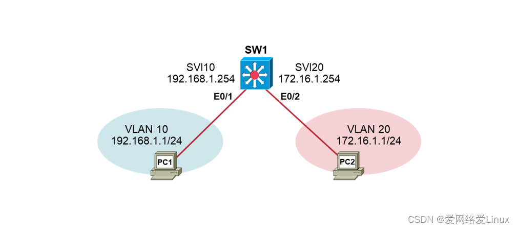
实验需求
- 根据实验拓扑图,完成设备的基本配置;
- 通过三层交换机的SVI实现VLAN10和VLAN20的互访。
实验步骤
步骤1:设备的基本配置
配置PC1:
VPCS> set pcname PC1 //设置主机名
PC1> ip 192.168.1.1/24 192.168.1.254 //设置IP地址与网关
配置PC2:
VPCS> set pcname PC2
PC2> ip 172.16.1.1/24 172.16.1.254
配置SW1:
Switch>enable
Switch#configure terminal
Switch(config)#hostname SW1
SW1(config)#no ip domain-lookup
SW1(config)#line console 0
SW1(config-line)#exec-timeout 0 0
SW1(config-line)#logging synchronous
SW1(config-line)#end
SW1#
步骤2:VLAN间路由的配置
配置SW1:
SW1(config)#vlan 10
SW1(config-vlan)#name IT
SW1(config-vlan)#exit
SW1(config)#vlan 20
SW1(config-vlan)#name HR
SW1(config-vlan)#exit
SW1(config)#interface Ethernet0/1
SW1(config-if)#switchport mode access
SW1(config-if)#switchport access vlan 10
SW1(config)#interface Ethernet0/2
SW1(config-if)#switchport mode access
SW1(config-if)#switchport access vlan 20
SW1(config-if)#exit
SW1(config)#interface vlan 10
SW1(config-if)#ip address 192.168.1.254 255.255.255.0
SW1(config-if)#no shutdown
SW1(config)#interface vlan 20
SW1(config-if)#ip address 172.16.1.254 255.255.255.0
SW1(config-if)#no shutdown
SW1(config)#ip routing
实验检查
检查SW1的接口状态:
SW1#show ip interface brief
Interface IP-Address OK? Method Status Protocol
Ethernet0/0 unassigned YES unset administratively down down
Ethernet0/1 unassigned YES unset up up
Ethernet0/2 unassigned YES unset up up
Ethernet0/3 unassigned YES unset up up
Vlan10 192.168.1.254 YES manual up up
Vlan20 172.16.1.254 YES manual up up
SVI10和SVI20状态正常。
测试网络的连通性:
PC1> ping 172.16.1.1
84 bytes from 172.16.1.1 icmp_seq=1 ttl=63 time=2.123 ms
84 bytes from 172.16.1.1 icmp_seq=2 ttl=63 time=0.626 ms
84 bytes from 172.16.1.1 icmp_seq=3 ttl=63 time=0.533 ms
84 bytes from 172.16.1.1 icmp_seq=4 ttl=63 time=0.466 ms
84 bytes from 172.16.1.1 icmp_seq=5 ttl=63 time=0.505 ms
PC1> trace 172.16.1.1
trace to 172.16.1.1, 8 hops max, press Ctrl+C to stop
1 192.168.1.254 0.758 ms 0.285 ms 0.736 ms
2 *172.16.1.1 0.636 ms (ICMP type:3, code:3, Destination port unreachable)
实验12:配置静态路由
实验目的
- 了解静态路由的原理
- 掌握静态路由的配置
实验任务
- 任务1
- 任务2

任务1:实验拓扑

任务1:实验需求
- 根据实验拓扑图,完成设备的基本配置;
- 在路由器R1、R2、R3上配置静态路由,保证全网路由可达;
任务1:实验步骤
步骤1:设备的基本配置
配置PC1:
VPCS> set pcname PC1 //设置主机名
PC1> ip 192.168.1.1/24 192.168.1.254 //设置IP地址与网关
配置PC2:
VPCS> set pcname PC2
PC2> ip 192.168.2.1/24 192.168.2.254
配置R1:
Router>enable
Router#configure terminal
Router(config)#hostname R1
R1(config)#no ip domain-lookup
R1(config)#line console 0
R1(config-line)#exec-timeout 0 0
R1(config-line)#logging synchronous
R1(config-line)#exit
R1(config)#interface ethernet0/0
R1(config-if)#ip address 192.168.1.254 255.255.255.0
R1(config-if)#no shutdown
R1(config-if)#exit
R1(config)#interface serial1/0
R1(config-if)#ip address 192.168.12.1 255.255.255.0
R1(config-if)#no shutdown
R1(config-if)#end
R1#
配置R2:
Router>enable
Router#configure terminal
Router(config)#hostname R2
R2(config)#no ip domain-lookup
R2(config)#line console 0
R2(config-line)#exec-timeout 0 0
R2(config-line)#logging synchronous
R2(config-line)#exit
R2(config)#interface serial1/0
R2(config-if)#ip address 192.168.12.2 255.255.255.0
R2(config-if)#no shutdown
R2(config-if)#exit
R2(config)#interface serial1/1
R2(config-if)#ip address 192.168.23.2 255.255.255.0
R2(config-if)#no shutdown
R2(config-if)#end
R2#
配置R3:
Router>enable
Router#configure terminal
Router(config)#hostname R3
R3(config)#no ip domain-lookup
R3(config)#line console 0
R3(config-line)#exec-timeout 0 0
R3(config-line)#logging synchronous
R3(config-line)#exit
R3(config)#interface ethernet0/0
R3(config-if)#ip address 192.168.2.254 255.255.255.0
R3(config-if)#no shutdown
R3(config-if)#exit
R3(config)#interface serial1/0
R3(config-if)#ip address 192.168.23.3 255.255.255.0
R3(config-if)#no shutdown
R3(config-if)#end
R3#
步骤2:检查设备接口状态
检查PC1:
PC1> show ip
NAME : PC1[1]
IP/MASK : 192.168.1.1/24
GATEWAY : 192.168.1.254
DNS :
MAC : 00:50:79:66:68:04
LPORT : 20000
RHOST:PORT : 127.0.0.1:30000
MTU : 1500
检查R1:
R1#show ip interface brief
Interface IP-Address OK? Method Status Protocol
Ethernet0/0 192.168.1.254 YES manual up up
Ethernet0/1 unassigned YES unset administratively down down
Ethernet0/2 unassigned YES unset administratively down down
Ethernet0/3 unassigned YES unset administratively down down
Serial1/0 192.168.12.1 YES manual up up
Serial1/1 unassigned YES unset administratively down down
Serial1/2 unassigned YES unset administratively down down
Serial1/3 unassigned YES unset administratively down down
检查R2:
R2#show ip interface brief
Interface IP-Address OK? Method Status Protocol
Ethernet0/0 unassigned YES unset administratively down down
Ethernet0/1 unassigned YES unset administratively down down
Ethernet0/2 unassigned YES unset administratively down down
Ethernet0/3 unassigned YES unset administratively down down
Serial1/0 192.168.12.2 YES manual up up
Serial1/1 192.168.23.2 YES manual up up
Serial1/2 unassigned YES unset administratively down down
Serial1/3 unassigned YES unset administratively down down
检查R3:
R3#show ip interface brief
Interface IP-Address OK? Method Status Protocol
Ethernet0/0 192.168.2.254 YES manual up up
Ethernet0/1 unassigned YES unset administratively down down
Ethernet0/2 unassigned YES unset administratively down down
Ethernet0/3 unassigned YES unset administratively down down
Serial1/0 192.168.23.3 YES manual up up
Serial1/1 unassigned YES unset administratively down down
Serial1/2 unassigned YES unset administratively down down
Serial1/3 unassigned YES unset administratively down down
检查PC2:
PC2> show ip
NAME : PC2[1]
IP/MASK : 192.168.2.1/24
GATEWAY : 192.168.2.254
DNS :
MAC : 00:50:79:66:68:05
LPORT : 20000
RHOST:PORT : 127.0.0.1:30000
MTU : 1500
步骤3:测试直连网络的连通性
测试PC1跟网关的网络连通性:
PC1> ping 192.168.1.254
84 bytes from 192.168.1.254 icmp_seq=1 ttl=255 time=0.359 ms
84 bytes from 192.168.1.254 icmp_seq=2 ttl=255 time=0.459 ms
84 bytes from 192.168.1.254 icmp_seq=3 ttl=255 time=0.463 ms
84 bytes from 192.168.1.254 icmp_seq=4 ttl=255 time=0.403 ms
84 bytes from 192.168.1.254 icmp_seq=5 ttl=255 time=0.417 ms
测试R1跟R2之间的网络连通性:
R1#ping 192.168.12.2
Type escape sequence to abort.
Sending 5, 100-byte ICMP Echos to 192.168.12.2, timeout is 2 seconds:
!!!!!
Success rate is 100 percent (5/5), round-trip min/avg/max = 8/9/10 ms
测试R2跟R3之间的网络连通性:
R2#ping 192.168.23.3
Type escape sequence to abort.
Sending 5, 100-byte ICMP Echos to 192.168.23.3, timeout is 2 seconds:
!!!!!
Success rate is 100 percent (5/5), round-trip min/avg/max = 9/9/11 ms
测试PC2跟网关的网络连通性:
PC2> ping 192.168.2.254
84 bytes from 192.168.2.254 icmp_seq=1 ttl=255 time=0.469 ms
84 bytes from 192.168.2.254 icmp_seq=2 ttl=255 time=0.484 ms
84 bytes from 192.168.2.254 icmp_seq=3 ttl=255 time=0.518 ms
84 bytes from 192.168.2.254 icmp_seq=4 ttl=255 time=0.400 ms
84 bytes from 192.168.2.254 icmp_seq=5 ttl=255 time=0.405 ms
注意,虽然设备之间的网络连通性正常了,但是PC1和PC2之间的网络是不可达的:
PC1> ping 192.168.2.1
*192.168.1.254 icmp_seq=1 ttl=255 time=0.345 ms (ICMP type:3, code:1, Destination host unreachable)
*192.168.1.254 icmp_seq=2 ttl=255 time=0.462 ms (ICMP type:3, code:1, Destination host unreachable)
*192.168.1.254 icmp_seq=3 ttl=255 time=0.543 ms (ICMP type:3, code:1, Destination host unreachable)
*192.168.1.254 icmp_seq=4 ttl=255 time=0.494 ms (ICMP type:3, code:1, Destination host unreachable)
*192.168.1.254 icmp_seq=5 ttl=255 time=0.467 ms (ICMP type:3, code:1, Destination host unreachable)
因为PC1把数据包发送给R1后,R1没有到达网络192.168.2.0/24的路由,所以R1无法转发数据包。
检查R1的路由表:
R1#show ip route
Codes: L - local, C - connected, S - static, R - RIP, M - mobile, B - BGP
D - EIGRP, EX - EIGRP external, O - OSPF, IA - OSPF inter area
N1 - OSPF NSSA external type 1, N2 - OSPF NSSA external type 2
E1 - OSPF external type 1, E2 - OSPF external type 2
i - IS-IS, su - IS-IS summary, L1 - IS-IS level-1, L2 - IS-IS level-2
ia - IS-IS inter area, * - candidate default, U - per-user static route
o - ODR, P - periodic downloaded static route, H - NHRP, l - LISP
a - application route
+ - replicated route, % - next hop override, p - overrides from PfR
Gateway of last resort is not set
192.168.1.0/24 is variably subnetted, 2 subnets, 2 masks
C 192.168.1.0/24 is directly connected, Ethernet0/0
L 192.168.1.254/32 is directly connected, Ethernet0/0
192.168.12.0/24 is variably subnetted, 2 subnets, 2 masks
C 192.168.12.0/24 is directly connected, Serial1/0
L 192.168.12.1/32 is directly connected, Serial1/0
R1只有两条直连路由,分别是192.168.1.0/24和192.168.12.0/24。
因此,我们需要在R1上配置去往192.168.2.0/24的静态路由。
步骤4:配置静态路由
配置R1:
R1(config)#ip route 192.168.2.0 255.255.255.0 192.168.12.2
//当然也可以跟出接口
路由要有去有回网络才能通,所以R3上要配置回程路由。
配置R3:
R3(config)#ip route 192.168.1.0 255.255.255.0 serial 1/0
//当然也可以跟下一跳
另外,沿途的路由器也要有去往源和目标网络的路由。
配置R2:
R2(config)#ip route 192.168.1.0 255.255.255.0 192.168.12.1
//当然也可以跟出接口
R2(config)#ip route 192.168.2.0 255.255.255.0 192.168.23.3
//当然也可以跟出接口
这样当PC1把数据包发送给R1时,R1查路由表:
R1#show ip route
Codes: L - local, C - connected, S - static, R - RIP, M - mobile, B - BGP
D - EIGRP, EX - EIGRP external, O - OSPF, IA - OSPF inter area
N1 - OSPF NSSA external type 1, N2 - OSPF NSSA external type 2
E1 - OSPF external type 1, E2 - OSPF external type 2
i - IS-IS, su - IS-IS summary, L1 - IS-IS level-1, L2 - IS-IS level-2
ia - IS-IS inter area, * - candidate default, U - per-user static route
o - ODR, P - periodic downloaded static route, H - NHRP, l - LISP
a - application route
+ - replicated route, % - next hop override, p - overrides from PfR
Gateway of last resort is not set
192.168.1.0/24 is variably subnetted, 2 subnets, 2 masks
C 192.168.1.0/24 is directly connected, Ethernet0/0
L 192.168.1.254/32 is directly connected, Ethernet0/0
S 192.168.2.0/24 [1/0] via 192.168.12.2
192.168.12.0/24 is variably subnetted, 2 subnets, 2 masks
C 192.168.12.0/24 is directly connected, Serial1/0
L 192.168.12.1/32 is directly connected, Serial1/0
R1有到达网络192.168.2.0/24的路由,所以R1把数据包发送给下一跳R2,R2检查路由表:
R2#show ip route
Codes: L - local, C - connected, S - static, R - RIP, M - mobile, B - BGP
D - EIGRP, EX - EIGRP external, O - OSPF, IA - OSPF inter area
N1 - OSPF NSSA external type 1, N2 - OSPF NSSA external type 2
E1 - OSPF external type 1, E2 - OSPF external type 2
i - IS-IS, su - IS-IS summary, L1 - IS-IS level-1, L2 - IS-IS level-2
ia - IS-IS inter area, * - candidate default, U - per-user static route
o - ODR, P - periodic downloaded static route, H - NHRP, l - LISP
a - application route
+ - replicated route, % - next hop override, p - overrides from PfR
Gateway of last resort is not set
S 192.168.1.0/24 [1/0] via 192.168.12.1
S 192.168.2.0/24 [1/0] via 192.168.23.3
192.168.12.0/24 is variably subnetted, 2 subnets, 2 masks
C 192.168.12.0/24 is directly connected, Serial1/0
L 192.168.12.2/32 is directly connected, Serial1/0
192.168.23.0/24 is variably subnetted, 2 subnets, 2 masks
C 192.168.23.0/24 is directly connected, Serial1/1
L 192.168.23.2/32 is directly connected, Serial1/1
R2有到达网络192.168.2.0/24的路由,所以R2把数据包发送给下一跳R3,R3检查路由表:
R3#show ip route
Codes: L - local, C - connected, S - static, R - RIP, M - mobile, B - BGP
D - EIGRP, EX - EIGRP external, O - OSPF, IA - OSPF inter area
N1 - OSPF NSSA external type 1, N2 - OSPF NSSA external type 2
E1 - OSPF external type 1, E2 - OSPF external type 2
i - IS-IS, su - IS-IS summary, L1 - IS-IS level-1, L2 - IS-IS level-2
ia - IS-IS inter area, * - candidate default, U - per-user static route
o - ODR, P - periodic downloaded static route, H - NHRP, l - LISP
a - application route
+ - replicated route, % - next hop override, p - overrides from PfR
Gateway of last resort is not set
S 192.168.1.0/24 is directly connected, Serial1/0
192.168.2.0/24 is variably subnetted, 2 subnets, 2 masks
C 192.168.2.0/24 is directly connected, Ethernet0/0
L 192.168.2.254/32 is directly connected, Ethernet0/0
192.168.23.0/24 is variably subnetted, 2 subnets, 2 masks
C 192.168.23.0/24 is directly connected, Serial1/0
L 192.168.23.3/32 is directly connected, Serial1/0
R3上192.168.2.0/24是自己的直连网络,所以R3把数据包直接发给PC2。
回程数据包的转发原理一样,这里不再撰述。
步骤5:测试PC1跟PC2的网络连通性
PC1> ping 192.168.2.1
84 bytes from 192.168.2.1 icmp_seq=1 ttl=61 time=22.503 ms
84 bytes from 192.168.2.1 icmp_seq=2 ttl=61 time=18.859 ms
84 bytes from 192.168.2.1 icmp_seq=3 ttl=61 time=19.251 ms
84 bytes from 192.168.2.1 icmp_seq=4 ttl=61 time=19.350 ms
84 bytes from 192.168.2.1 icmp_seq=5 ttl=61 time=17.856 ms
因为需求要求全网路由可达;
如果这个时候在R1上Ping PC2,能不能通呢?不能!
在R1上Ping PC2,数据包源地址是192.168.12.1,数据包能到达PC2,但是回不来,因为R3上没有到达192.168.12.0/24的路由;
同理,R3上Ping PC1也不通,因为R1没有到达192.168.23.0/24的路由。
检查R3的路由表:
R3#show ip route
Codes: L - local, C - connected, S - static, R - RIP, M - mobile, B - BGP
D - EIGRP, EX - EIGRP external, O - OSPF, IA - OSPF inter area
N1 - OSPF NSSA external type 1, N2 - OSPF NSSA external type 2
E1 - OSPF external type 1, E2 - OSPF external type 2
i - IS-IS, su - IS-IS summary, L1 - IS-IS level-1, L2 - IS-IS level-2
ia - IS-IS inter area, * - candidate default, U - per-user static route
o - ODR, P - periodic downloaded static route, H - NHRP, l - LISP
a - application route
+ - replicated route, % - next hop override, p - overrides from PfR
Gateway of last resort is not set
S 192.168.1.0/24 is directly connected, Serial1/0
192.168.2.0/24 is variably subnetted, 2 subnets, 2 masks
C 192.168.2.0/24 is directly connected, Ethernet0/0
L 192.168.2.254/32 is directly connected, Ethernet0/0
192.168.23.0/24 is variably subnetted, 2 subnets, 2 masks
C 192.168.23.0/24 is directly connected, Serial1/0
L 192.168.23.3/32 is directly connected, Serial1/0
R3没有到达网络192.168.12.0/24的路由。
配置R3:
R3(config)#ip route 192.168.12.0 255.255.255.0 192.168.23.2
//当然也可以跟出接口
同理,配置R1:
R1(config)#ip route 192.168.23.0 255.255.255.0 serial 1/0
//当然也可以跟下一跳
检查R1的路由表:
R1#show ip route
Codes: L - local, C - connected, S - static, R - RIP, M - mobile, B - BGP
D - EIGRP, EX - EIGRP external, O - OSPF, IA - OSPF inter area
N1 - OSPF NSSA external type 1, N2 - OSPF NSSA external type 2
E1 - OSPF external type 1, E2 - OSPF external type 2
i - IS-IS, su - IS-IS summary, L1 - IS-IS level-1, L2 - IS-IS level-2
ia - IS-IS inter area, * - candidate default, U - per-user static route
o - ODR, P - periodic downloaded static route, H - NHRP, l - LISP
a - application route
+ - replicated route, % - next hop override, p - overrides from PfR
Gateway of last resort is not set
192.168.1.0/24 is variably subnetted, 2 subnets, 2 masks
C 192.168.1.0/24 is directly connected, Ethernet0/0
L 192.168.1.254/32 is directly connected, Ethernet0/0
S 192.168.2.0/24 [1/0] via 192.168.12.2
192.168.12.0/24 is variably subnetted, 2 subnets, 2 masks
C 192.168.12.0/24 is directly connected, Serial1/0
L 192.168.12.1/32 is directly connected, Serial1/0
S 192.168.23.0/24 is directly connected, Serial1/0
R1有到达192.168.2.0/24和192.168.23.0/24的路由。
检查R3的路由表:
R3#show ip route
Codes: L - local, C - connected, S - static, R - RIP, M - mobile, B - BGP
D - EIGRP, EX - EIGRP external, O - OSPF, IA - OSPF inter area
N1 - OSPF NSSA external type 1, N2 - OSPF NSSA external type 2
E1 - OSPF external type 1, E2 - OSPF external type 2
i - IS-IS, su - IS-IS summary, L1 - IS-IS level-1, L2 - IS-IS level-2
ia - IS-IS inter area, * - candidate default, U - per-user static route
o - ODR, P - periodic downloaded static route, H - NHRP, l - LISP
a - application route
+ - replicated route, % - next hop override, p - overrides from PfR
Gateway of last resort is not set
S 192.168.1.0/24 is directly connected, Serial1/0
192.168.2.0/24 is variably subnetted, 2 subnets, 2 masks
C 192.168.2.0/24 is directly connected, Ethernet0/0
L 192.168.2.254/32 is directly connected, Ethernet0/0
S 192.168.12.0/24 [1/0] via 192.168.23.2
192.168.23.0/24 is variably subnetted, 2 subnets, 2 masks
C 192.168.23.0/24 is directly connected, Serial1/0
L 192.168.23.3/32 is directly connected, Serial1/0
R3有到达192.168.1.0/24和192.168.12.0/24的路由。
步骤6:测试网络连通性
在PC1上测试:
PC1> ping 192.168.2.1
84 bytes from 192.168.2.1 icmp_seq=1 ttl=61 time=21.429 ms
84 bytes from 192.168.2.1 icmp_seq=2 ttl=61 time=18.079 ms
84 bytes from 192.168.2.1 icmp_seq=3 ttl=61 time=19.108 ms
84 bytes from 192.168.2.1 icmp_seq=4 ttl=61 time=19.006 ms
84 bytes from 192.168.2.1 icmp_seq=5 ttl=61 time=18.163 ms
PC1> ping 192.168.23.3
84 bytes from 192.168.23.3 icmp_seq=1 ttl=253 time=18.265 ms
84 bytes from 192.168.23.3 icmp_seq=2 ttl=253 time=18.186 ms
84 bytes from 192.168.23.3 icmp_seq=3 ttl=253 time=18.184 ms
84 bytes from 192.168.23.3 icmp_seq=4 ttl=253 time=18.257 ms
84 bytes from 192.168.23.3 icmp_seq=5 ttl=253 time=18.240 ms
PC1> ping 192.168.12.2
84 bytes from 192.168.12.2 icmp_seq=1 ttl=254 time=9.899 ms
84 bytes from 192.168.12.2 icmp_seq=2 ttl=254 time=9.380 ms
84 bytes from 192.168.12.2 icmp_seq=3 ttl=254 time=9.159 ms
84 bytes from 192.168.12.2 icmp_seq=4 ttl=254 time=9.300 ms
84 bytes from 192.168.12.2 icmp_seq=5 ttl=254 time=9.268 ms
任务2:实验拓扑

任务2:实验需求
- 在R1和R3上删除任务1的静态路由;
- 在路由器R1、R3上配置默认路由,使得全网路由可达。
任务2:实验步骤
步骤1:删除R1和R3上的静态路由并配置默认路由
配置R1:
R1(config)#no ip route 192.168.2.0 255.255.255.0 192.168.12.2
R1(config)#no ip route 192.168.23.0 255.255.255.0 Serial1/0
R1(config)#ip route 0.0.0.0 0.0.0.0 192.168.12.2
配置R3:
R3(config)#no ip route 192.168.1.0 255.255.255.0 Serial1/0
R3(config)#no ip route 192.168.12.0 255.255.255.0 192.168.23.2
R3(config)#ip route 0.0.0.0 0.0.0.0 192.168.23.2
步骤2:检查默认路由
检查R1:
R1#show ip route
Codes: L - local, C - connected, S - static, R - RIP, M - mobile, B - BGP
D - EIGRP, EX - EIGRP external, O - OSPF, IA - OSPF inter area
N1 - OSPF NSSA external type 1, N2 - OSPF NSSA external type 2
E1 - OSPF external type 1, E2 - OSPF external type 2
i - IS-IS, su - IS-IS summary, L1 - IS-IS level-1, L2 - IS-IS level-2
ia - IS-IS inter area, * - candidate default, U - per-user static route
o - ODR, P - periodic downloaded static route, H - NHRP, l - LISP
a - application route
+ - replicated route, % - next hop override, p - overrides from PfR
Gateway of last resort is 192.168.12.2 to network 0.0.0.0
S* 0.0.0.0/0 [1/0] via 192.168.12.2
192.168.1.0/24 is variably subnetted, 2 subnets, 2 masks
C 192.168.1.0/24 is directly connected, Ethernet0/0
L 192.168.1.254/32 is directly connected, Ethernet0/0
192.168.12.0/24 is variably subnetted, 2 subnets, 2 masks
C 192.168.12.0/24 is directly connected, Serial1/0
L 192.168.12.1/32 is directly connected, Serial1/0
检查R3:
R3#show ip route
Codes: L - local, C - connected, S - static, R - RIP, M - mobile, B - BGP
D - EIGRP, EX - EIGRP external, O - OSPF, IA - OSPF inter area
N1 - OSPF NSSA external type 1, N2 - OSPF NSSA external type 2
E1 - OSPF external type 1, E2 - OSPF external type 2
i - IS-IS, su - IS-IS summary, L1 - IS-IS level-1, L2 - IS-IS level-2
ia - IS-IS inter area, * - candidate default, U - per-user static route
o - ODR, P - periodic downloaded static route, H - NHRP, l - LISP
a - application route
+ - replicated route, % - next hop override, p - overrides from PfR
Gateway of last resort is 192.168.23.2 to network 0.0.0.0
S* 0.0.0.0/0 [1/0] via 192.168.23.2
192.168.2.0/24 is variably subnetted, 2 subnets, 2 masks
C 192.168.2.0/24 is directly connected, Ethernet0/0
L 192.168.2.254/32 is directly connected, Ethernet0/0
192.168.23.0/24 is variably subnetted, 2 subnets, 2 masks
C 192.168.23.0/24 is directly connected, Serial1/0
L 192.168.23.3/32 is directly connected, Serial1/0
步骤3:网络连通性测试
PC1> ping 192.168.2.1
84 bytes from 192.168.2.1 icmp_seq=1 ttl=61 time=20.698 ms
84 bytes from 192.168.2.1 icmp_seq=2 ttl=61 time=19.478 ms
84 bytes from 192.168.2.1 icmp_seq=3 ttl=61 time=18.593 ms
84 bytes from 192.168.2.1 icmp_seq=4 ttl=61 time=19.404 ms
84 bytes from 192.168.2.1 icmp_seq=5 ttl=61 time=19.616 ms
PC1> ping 192.168.23.3
84 bytes from 192.168.23.3 icmp_seq=1 ttl=253 time=22.048 ms
84 bytes from 192.168.23.3 icmp_seq=2 ttl=253 time=20.271 ms
84 bytes from 192.168.23.3 icmp_seq=3 ttl=253 time=19.362 ms
84 bytes from 192.168.23.3 icmp_seq=4 ttl=253 time=20.110 ms
84 bytes from 192.168.23.3 icmp_seq=5 ttl=253 time=21.321 ms
PC1> ping 192.168.12.2
84 bytes from 192.168.12.2 icmp_seq=1 ttl=254 time=10.201 ms
84 bytes from 192.168.12.2 icmp_seq=2 ttl=254 time=10.220 ms
84 bytes from 192.168.12.2 icmp_seq=3 ttl=254 time=8.304 ms
84 bytes from 192.168.12.2 icmp_seq=4 ttl=254 time=9.170 ms
84 bytes from 192.168.12.2 icmp_seq=5 ttl=254 time=10.084 ms
实验13:配置EIGRP
实验目的
- 了解EIGRP的运行原理
- 了解EIGRP自动汇总的原理
- 掌握EIGRP基本的配置方法
- 掌握EIGRP手工汇总的配置方法
实验任务
- 任务1
- 任务2
- 任务3
任务1:实验拓扑
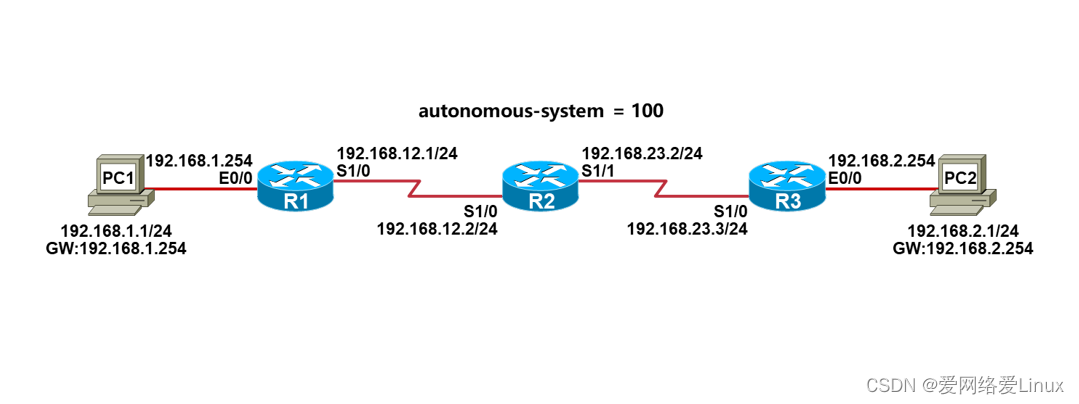
任务1:实验需求
- 根据实验拓扑图,完成设备的基本配置;
- 在R1、R2、R3上配置EIGRP,使得全网路由可达;
- 测试网络的连通性。
任务1:实验步骤
步骤1:设备的基本配置
配置PC1:
VPCS> set pcname PC1 //设置主机名
PC1> ip 192.168.1.1/24 192.168.1.254 //设置IP地址与网关
配置PC2:
VPCS> set pcname PC2
PC2> ip 192.168.2.1/24 192.168.2.254
配置R1:
Router>enable
Router#configure terminal
Router(config)#hostname R1
R1(config)#no ip domain-lookup
R1(config)#line console 0
R1(config-line)#exec-timeout 0 0
R1(config-line)#logging synchronous
R1(config-line)#exit
R1(config)#interface ethernet0/0
R1(config-if)#ip address 192.168.1.254 255.255.255.0
R1(config-if)#no shutdown
R1(config-if)#exit
R1(config)#interface serial1/0
R1(config-if)#ip address 192.168.12.1 255.255.255.0
R1(config-if)#no shutdown
R1(config-if)#end
R1#
配置R2:
Router>enable
Router#configure terminal
Router(config)#hostname R2
R2(config)#no ip domain-lookup
R2(config)#line console 0
R2(config-line)#exec-timeout 0 0
R2(config-line)#logging synchronous
R2(config-line)#exit
R2(config)#interface serial1/0
R2(config-if)#ip address 192.168.12.2 255.255.255.0
R2(config-if)#no shutdown
R2(config-if)#exit
R2(config)#interface serial1/1
R2(config-if)#ip address 192.168.23.2 255.255.255.0
R2(config-if)#no shutdown
R2(config-if)#end
R2#
配置R3:
Router>enable
Router#configure terminal
Router(config)#hostname R3
R3(config)#no ip domain-lookup
R3(config)#line console 0
R3(config-line)#exec-timeout 0 0
R3(config-line)#logging synchronous
R3(config-line)#exit
R3(config)#interface ethernet0/0
R3(config-if)#ip address 192.168.2.254 255.255.255.0
R3(config-if)#no shutdown
R3(config-if)#exit
R3(config)#interface serial1/0
R3(config-if)#ip address 192.168.23.3 255.255.255.0
R3(config-if)#no shutdown
R3(config-if)#end
R3#
步骤2:检查设备接口状态
检查PC1:
PC1> show ip
NAME : PC1[1]
IP/MASK : 192.168.1.1/24
GATEWAY : 192.168.1.254
DNS :
MAC : 00:50:79:66:68:04
LPORT : 20000
RHOST:PORT : 127.0.0.1:30000
MTU : 1500
检查R1:
R1#show ip interface brief
Interface IP-Address OK? Method Status Protocol
Ethernet0/0 192.168.1.254 YES manual up up
Ethernet0/1 unassigned YES unset administratively down down
Ethernet0/2 unassigned YES unset administratively down down
Ethernet0/3 unassigned YES unset administratively down down
Serial1/0 192.168.12.1 YES manual up up
Serial1/1 unassigned YES unset administratively down down
Serial1/2 unassigned YES unset administratively down down
Serial1/3 unassigned YES unset administratively down down
检查R2:
R2#show ip interface brief
Interface IP-Address OK? Method Status Protocol
Ethernet0/0 unassigned YES unset administratively down down
Ethernet0/1 unassigned YES unset administratively down down
Ethernet0/2 unassigned YES unset administratively down down
Ethernet0/3 unassigned YES unset administratively down down
Serial1/0 192.168.12.2 YES manual up up
Serial1/1 192.168.23.2 YES manual up up
Serial1/2 unassigned YES unset administratively down down
Serial1/3 unassigned YES unset administratively down down
检查R3:
R3#show ip interface brief
Interface IP-Address OK? Method Status Protocol
Ethernet0/0 192.168.2.254 YES manual up up
Ethernet0/1 unassigned YES unset administratively down down
Ethernet0/2 unassigned YES unset administratively down down
Ethernet0/3 unassigned YES unset administratively down down
Serial1/0 192.168.23.3 YES manual up up
Serial1/1 unassigned YES unset administratively down down
Serial1/2 unassigned YES unset administratively down down
Serial1/3 unassigned YES unset administratively down down
检查PC2:
PC2> show ip
NAME : PC2[1]
IP/MASK : 192.168.2.1/24
GATEWAY : 192.168.2.254
DNS :
MAC : 00:50:79:66:68:05
LPORT : 20000
RHOST:PORT : 127.0.0.1:30000
MTU : 1500
步骤3:测试直连网络的连通性
测试PC1跟网关的网络连通性:
PC1> ping 192.168.1.254
84 bytes from 192.168.1.254 icmp_seq=1 ttl=255 time=0.359 ms
84 bytes from 192.168.1.254 icmp_seq=2 ttl=255 time=0.459 ms
84 bytes from 192.168.1.254 icmp_seq=3 ttl=255 time=0.463 ms
84 bytes from 192.168.1.254 icmp_seq=4 ttl=255 time=0.403 ms
84 bytes from 192.168.1.254 icmp_seq=5 ttl=255 time=0.417 ms
测试R1跟R2之间的网络连通性:
R1#ping 192.168.12.2
Type escape sequence to abort.
Sending 5, 100-byte ICMP Echos to 192.168.12.2, timeout is 2 seconds:
!!!!!
Success rate is 100 percent (5/5), round-trip min/avg/max = 8/9/10 ms
测试R2跟R3之间的网络连通性:
R2#ping 192.168.23.3
Type escape sequence to abort.
Sending 5, 100-byte ICMP Echos to 192.168.23.3, timeout is 2 seconds:
!!!!!
Success rate is 100 percent (5/5), round-trip min/avg/max = 9/9/11 ms
测试PC2跟网关的网络连通性:
PC2> ping 192.168.2.254
84 bytes from 192.168.2.254 icmp_seq=1 ttl=255 time=0.469 ms
84 bytes from 192.168.2.254 icmp_seq=2 ttl=255 time=0.484 ms
84 bytes from 192.168.2.254 icmp_seq=3 ttl=255 time=0.518 ms
84 bytes from 192.168.2.254 icmp_seq=4 ttl=255 time=0.400 ms
84 bytes from 192.168.2.254 icmp_seq=5 ttl=255 time=0.405 ms
步骤4:配置EIGRP
配置R1:
R1(config)#router eigrp 100
R1(config-router)#network 192.168.1.0 0.0.0.255
R1(config-router)#network 192.168.12.0 0.0.0.255
R1(config-router)#end
R1#
配置R2:
R2(config)#router eigrp 100
R2(config-router)#network 192.168.12.0 0.0.0.255
R2(config-router)#network 192.168.23.0 0.0.0.255
R2(config-router)#end
R2#
配置R3:
R3(config)#router eigrp 100
R3(config-router)#network 192.168.23.0 0.0.0.255
R3(config-router)#network 192.168.2.0 0.0.0.255
R3(config-router)#end
R3#
步骤5:检查EIGRP路由
检查R1:
R1#show ip route
Codes: L - local, C - connected, S - static, R - RIP, M - mobile, B - BGP
D - EIGRP, EX - EIGRP external, O - OSPF, IA - OSPF inter area
N1 - OSPF NSSA external type 1, N2 - OSPF NSSA external type 2
E1 - OSPF external type 1, E2 - OSPF external type 2
i - IS-IS, su - IS-IS summary, L1 - IS-IS level-1, L2 - IS-IS level-2
ia - IS-IS inter area, * - candidate default, U - per-user static route
o - ODR, P - periodic downloaded static route, H - NHRP, l - LISP
a - application route
+ - replicated route, % - next hop override, p - overrides from PfR
Gateway of last resort is not set
192.168.1.0/24 is variably subnetted, 2 subnets, 2 masks
C 192.168.1.0/24 is directly connected, Ethernet0/0
L 192.168.1.254/32 is directly connected, Ethernet0/0
D 192.168.2.0/24 [90/2707456] via 192.168.12.2, 00:00:55, Serial1/0
192.168.12.0/24 is variably subnetted, 2 subnets, 2 masks
C 192.168.12.0/24 is directly connected, Serial1/0
L 192.168.12.1/32 is directly connected, Serial1/0
D 192.168.23.0/24 [90/2681856] via 192.168.12.2, 00:01:34, Serial1/0
检查R2:
R2#show ip route
Codes: L - local, C - connected, S - static, R - RIP, M - mobile, B - BGP
D - EIGRP, EX - EIGRP external, O - OSPF, IA - OSPF inter area
N1 - OSPF NSSA external type 1, N2 - OSPF NSSA external type 2
E1 - OSPF external type 1, E2 - OSPF external type 2
i - IS-IS, su - IS-IS summary, L1 - IS-IS level-1, L2 - IS-IS level-2
ia - IS-IS inter area, * - candidate default, U - per-user static route
o - ODR, P - periodic downloaded static route, H - NHRP, l - LISP
a - application route
+ - replicated route, % - next hop override, p - overrides from PfR
Gateway of last resort is not set
D 192.168.1.0/24 [90/2195456] via 192.168.12.1, 00:02:26, Serial1/0
D 192.168.2.0/24 [90/2195456] via 192.168.23.3, 00:01:24, Serial1/1
192.168.12.0/24 is variably subnetted, 2 subnets, 2 masks
C 192.168.12.0/24 is directly connected, Serial1/0
L 192.168.12.2/32 is directly connected, Serial1/0
192.168.23.0/24 is variably subnetted, 2 subnets, 2 masks
C 192.168.23.0/24 is directly connected, Serial1/1
L 192.168.23.2/32 is directly connected, Serial1/1
检查R3:
R3#show ip route
Codes: L - local, C - connected, S - static, R - RIP, M - mobile, B - BGP
D - EIGRP, EX - EIGRP external, O - OSPF, IA - OSPF inter area
N1 - OSPF NSSA external type 1, N2 - OSPF NSSA external type 2
E1 - OSPF external type 1, E2 - OSPF external type 2
i - IS-IS, su - IS-IS summary, L1 - IS-IS level-1, L2 - IS-IS level-2
ia - IS-IS inter area, * - candidate default, U - per-user static route
o - ODR, P - periodic downloaded static route, H - NHRP, l - LISP
a - application route
+ - replicated route, % - next hop override, p - overrides from PfR
Gateway of last resort is not set
D 192.168.1.0/24 [90/2707456] via 192.168.23.2, 00:01:55, Serial1/0
192.168.2.0/24 is variably subnetted, 2 subnets, 2 masks
C 192.168.2.0/24 is directly connected, Ethernet0/0
L 192.168.2.254/32 is directly connected, Ethernet0/0
D 192.168.12.0/24 [90/2681856] via 192.168.23.2, 00:01:55, Serial1/0
192.168.23.0/24 is variably subnetted, 2 subnets, 2 masks
C 192.168.23.0/24 is directly connected, Serial1/0
L 192.168.23.3/32 is directly connected, Serial1/0
步骤6:测试网络的连通性
测试PC1:
PC1> ping 192.168.2.1
84 bytes from 192.168.2.1 icmp_seq=1 ttl=61 time=21.438 ms
84 bytes from 192.168.2.1 icmp_seq=2 ttl=61 time=14.345 ms
84 bytes from 192.168.2.1 icmp_seq=3 ttl=61 time=19.706 ms
84 bytes from 192.168.2.1 icmp_seq=4 ttl=61 time=18.968 ms
84 bytes from 192.168.2.1 icmp_seq=5 ttl=61 time=19.006 ms
PC1> ping 192.168.23.3
84 bytes from 192.168.23.3 icmp_seq=1 ttl=253 time=18.992 ms
84 bytes from 192.168.23.3 icmp_seq=2 ttl=253 time=18.513 ms
84 bytes from 192.168.23.3 icmp_seq=3 ttl=253 time=18.559 ms
84 bytes from 192.168.23.3 icmp_seq=4 ttl=253 time=18.514 ms
84 bytes from 192.168.23.3 icmp_seq=5 ttl=253 time=15.974 ms
PC1> ping 192.168.12.2
84 bytes from 192.168.12.2 icmp_seq=1 ttl=254 time=9.668 ms
84 bytes from 192.168.12.2 icmp_seq=2 ttl=254 time=9.340 ms
84 bytes from 192.168.12.2 icmp_seq=3 ttl=254 time=9.307 ms
84 bytes from 192.168.12.2 icmp_seq=4 ttl=254 time=9.189 ms
84 bytes from 192.168.12.2 icmp_seq=5 ttl=254 time=9.086 ms
任务2:实验拓扑

任务2:实验需求
- 根据实验拓扑图,完成设备的基本配置;
- 在R1和R3上分别创建Lo1、Lo2、Lo3,IP地址如图所示,并宣告进EIGRP;
- 在R1、R2、R3上配置EIGRP,打开自动汇总,保证全网路由可达。
任务2:实验步骤
步骤1:设备的基本配置
配置PC1:
VPCS> set pcname PC1 //设置主机名
PC1> ip 192.168.1.1/24 192.168.1.254 //设置IP地址与网关
配置PC2:
VPCS> set pcname PC2
PC2> ip 192.168.2.1/24 192.168.2.254
配置R1:
Router>enable
Router#configure terminal
Router(config)#hostname R1
R1(config)#no ip domain-lookup
R1(config)#line console 0
R1(config-line)#exec-timeout 0 0
R1(config-line)#logging synchronous
R1(config-line)#exit
R1(config)#interface loopback 1
R1(config-if)#ip address 172.16.1.1 255.255.255.0
R1(config-if)#exit
R1(config)#interface loopback 2
R1(config-if)#ip address 172.16.2.1 255.255.255.0
R1(config-if)#exit
R1(config)#interface loopback 3
R1(config-if)#ip address 172.16.3.1 255.255.255.0
R1(config-if)#exit
R1(config)#interface ethernet0/0
R1(config-if)#ip address 192.168.1.254 255.255.255.0
R1(config-if)#no shutdown
R1(config-if)#exit
R1(config)#interface serial1/0
R1(config-if)#ip address 192.168.12.1 255.255.255.0
R1(config-if)#no shutdown
R1(config-if)#end
R1#
配置R2:
Router>enable
Router#configure terminal
Router(config)#hostname R2
R2(config)#no ip domain-lookup
R2(config)#line console 0
R2(config-line)#exec-timeout 0 0
R2(config-line)#logging synchronous
R2(config-line)#exit
R2(config)#interface serial1/0
R2(config-if)#ip address 192.168.12.2 255.255.255.0
R2(config-if)#no shutdown
R2(config-if)#exit
R2(config)#interface serial1/1
R2(config-if)#ip address 192.168.23.2 255.255.255.0
R2(config-if)#no shutdown
R2(config-if)#end
R2#
配置R3:
Router>enable
Router#configure terminal
Router(config)#hostname R3
R3(config)#no ip domain-lookup
R3(config)#line console 0
R3(config-line)#exec-timeout 0 0
R3(config-line)#logging synchronous
R3(config-line)#exit
R3(config)#interface loopback 1
R3(config-if)#ip address 172.16.10.1 255.255.255.0
R3(config-if)#exit
R3(config)#interface loopback 2
R3(config-if)#ip address 172.16.20.1 255.255.255.0
R3(config-if)#exit
R3(config)#interface loopback 3
R3(config-if)#ip address 172.16.30.1 255.255.255.0
R3(config-if)#exit
R3(config)#interface ethernet0/0
R3(config-if)#ip address 192.168.2.254 255.255.255.0
R3(config-if)#no shutdown
R3(config-if)#exit
R3(config)#interface serial1/0
R3(config-if)#ip address 192.168.23.3 255.255.255.0
R3(config-if)#no shutdown
R3(config-if)#end
R3#
步骤2:检查设备接口状态
检查PC1:
PC1> show ip
NAME : PC1[1]
IP/MASK : 192.168.1.1/24
GATEWAY : 192.168.1.254
DNS :
MAC : 00:50:79:66:68:04
LPORT : 20000
RHOST:PORT : 127.0.0.1:30000
MTU : 1500
检查R1:
R1#show ip interface brief
Interface IP-Address OK? Method Status Protocol
Ethernet0/0 192.168.1.254 YES manual up up
Ethernet0/1 unassigned YES unset administratively down down
Ethernet0/2 unassigned YES unset administratively down down
Ethernet0/3 unassigned YES unset administratively down down
Serial1/0 192.168.12.1 YES manual up up
Serial1/1 unassigned YES unset administratively down down
Serial1/2 unassigned YES unset administratively down down
Serial1/3 unassigned YES unset administratively down down
检查R2:
R2#show ip interface brief
Interface IP-Address OK? Method Status Protocol
Ethernet0/0 unassigned YES unset administratively down down
Ethernet0/1 unassigned YES unset administratively down down
Ethernet0/2 unassigned YES unset administratively down down
Ethernet0/3 unassigned YES unset administratively down down
Serial1/0 192.168.12.2 YES manual up up
Serial1/1 192.168.23.2 YES manual up up
Serial1/2 unassigned YES unset administratively down down
Serial1/3 unassigned YES unset administratively down down
检查R3:
R3#show ip interface brief
Interface IP-Address OK? Method Status Protocol
Ethernet0/0 192.168.2.254 YES manual up up
Ethernet0/1 unassigned YES unset administratively down down
Ethernet0/2 unassigned YES unset administratively down down
Ethernet0/3 unassigned YES unset administratively down down
Serial1/0 192.168.23.3 YES manual up up
Serial1/1 unassigned YES unset administratively down down
Serial1/2 unassigned YES unset administratively down down
Serial1/3 unassigned YES unset administratively down down
检查PC2:
PC2> show ip
NAME : PC2[1]
IP/MASK : 192.168.2.1/24
GATEWAY : 192.168.2.254
DNS :
MAC : 00:50:79:66:68:05
LPORT : 20000
RHOST:PORT : 127.0.0.1:30000
MTU : 1500
步骤3:测试直连网络的连通性
测试PC1跟网关的网络连通性:
PC1> ping 192.168.1.254
84 bytes from 192.168.1.254 icmp_seq=1 ttl=255 time=0.359 ms
84 bytes from 192.168.1.254 icmp_seq=2 ttl=255 time=0.459 ms
84 bytes from 192.168.1.254 icmp_seq=3 ttl=255 time=0.463 ms
84 bytes from 192.168.1.254 icmp_seq=4 ttl=255 time=0.403 ms
84 bytes from 192.168.1.254 icmp_seq=5 ttl=255 time=0.417 ms
测试R1跟R2之间的网络连通性:
R1#ping 192.168.12.2
Type escape sequence to abort.
Sending 5, 100-byte ICMP Echos to 192.168.12.2, timeout is 2 seconds:
!!!!!
Success rate is 100 percent (5/5), round-trip min/avg/max = 8/9/10 ms
测试R2跟R3之间的网络连通性:
R2#ping 192.168.23.3
Type escape sequence to abort.
Sending 5, 100-byte ICMP Echos to 192.168.23.3, timeout is 2 seconds:
!!!!!
Success rate is 100 percent (5/5), round-trip min/avg/max = 9/9/11 ms
测试PC2跟网关的网络连通性:
PC2> ping 192.168.2.254
84 bytes from 192.168.2.254 icmp_seq=1 ttl=255 time=0.469 ms
84 bytes from 192.168.2.254 icmp_seq=2 ttl=255 time=0.484 ms
84 bytes from 192.168.2.254 icmp_seq=3 ttl=255 time=0.518 ms
84 bytes from 192.168.2.254 icmp_seq=4 ttl=255 time=0.400 ms
84 bytes from 192.168.2.254 icmp_seq=5 ttl=255 time=0.405 ms
步骤4:打开EIGRP自动汇总
配置R1:
R1(config)#router eigrp 100
R1(config-router)#auto-summary
R1(config-router)#network 172.16.1.0 0.0.0.255
R1(config-router)#network 172.16.2.0 0.0.0.255
R1(config-router)#network 172.16.3.0 0.0.0.255
R1(config-router)#network 192.168.1.0 0.0.0.255
R1(config-router)#network 192.168.12.0 0.0.0.255
R1(config-router)#end
R1#
配置R2:
R2(config)#router eigrp 100
R2(config-router)#auto-summary
R2(config-router)#network 192.168.12.0 0.0.0.255
R2(config-router)#network 192.168.23.0 0.0.0.255
R2(config-router)#end
R2#
配置R3:
R3(config)#router eigrp 100
R3(config-router)#auto-summary
R3(config-router)#network 172.16.10.0 0.0.0.255
R3(config-router)#network 172.16.20.0 0.0.0.255
R3(config-router)#network 172.16.30.0 0.0.0.255
R3(config-router)#network 192.168.23.0 0.0.0.255
R3(config-router)#network 192.168.2.0 0.0.0.255
R3(config-router)#end
R3#
步骤5:检查EIGRP路由
检查R2:
R2#show ip route
Codes: L - local, C - connected, S - static, R - RIP, M - mobile, B - BGP
D - EIGRP, EX - EIGRP external, O - OSPF, IA - OSPF inter area
N1 - OSPF NSSA external type 1, N2 - OSPF NSSA external type 2
E1 - OSPF external type 1, E2 - OSPF external type 2
i - IS-IS, su - IS-IS summary, L1 - IS-IS level-1, L2 - IS-IS level-2
ia - IS-IS inter area, * - candidate default, U - per-user static route
o - ODR, P - periodic downloaded static route, H - NHRP, l - LISP
a - application route
+ - replicated route, % - next hop override, p - overrides from PfR
Gateway of last resort is not set
D 172.16.0.0/16 [90/2297856] via 192.168.23.3, 00:02:53, Serial1/1
[90/2297856] via 192.168.12.1, 00:02:53, Serial1/0
D 192.168.1.0/24 [90/2195456] via 192.168.12.1, 00:19:55, Serial1/0
D 192.168.2.0/24 [90/2195456] via 192.168.23.3, 00:18:53, Serial1/1
192.168.12.0/24 is variably subnetted, 2 subnets, 2 masks
C 192.168.12.0/24 is directly connected, Serial1/0
L 192.168.12.2/32 is directly connected, Serial1/0
192.168.23.0/24 is variably subnetted, 2 subnets, 2 masks
C 192.168.23.0/24 is directly connected, Serial1/1
L 192.168.23.2/32 is directly connected, Serial1/1
R2的路由表去往172.16.0.0/16是等价负载的,为什么?
EIGRP在自动汇总打开的情况下,在主类网络边界会执行自动汇总,将路由汇总成主类网络;
R1和R3的Lo1、Lo2、Lo3接口地址都是B类地址,所以R1和R3把它们汇总了B类网络,即,172.16.0.0/16。
假设这个时候R2有数据包要去往172.16.1.0/24或其它网络,那么有可能会出现以下情况:
R2#ping 172.16.1.1
Type escape sequence to abort.
Sending 5, 100-byte ICMP Echos to 172.16.1.1, timeout is 2 seconds:
U.U.U
Success rate is 0 percent (0/5)
R2#ping 172.16.2.1
Type escape sequence to abort.
Sending 5, 100-byte ICMP Echos to 172.16.2.1, timeout is 2 seconds:
!!!!!
Success rate is 100 percent (5/5), round-trip min/avg/max = 7/9/11 ms
因为路由是负载的,所以有可能有的网络通,有的网络不通。
怎么解决?关闭自动汇总!
步骤6:关闭EIGRP自动汇总
注意,12.X版本的IOS自动汇总默认打开,15.X版本的IOS自动汇总默认关闭。
配置R1:
R1(config)#router eigrp 100
R1(config-router)#no auto-summary
R1(config-router)#end
R1#
配置R2:
R2(config)#router eigrp 100
R2(config-router)#no auto-summary
R2(config-router)#end
R2#
配置R3:
R3(config)#router eigrp 100
R3(config-router)#no auto-summary
R3(config-router)#end
R3#
关闭自动汇总之后,R2的路由表看到的就是Loopback口的明细路由而不是汇总路由了。
检查R2:
R2#show ip route
Codes: L - local, C - connected, S - static, R - RIP, M - mobile, B - BGP
D - EIGRP, EX - EIGRP external, O - OSPF, IA - OSPF inter area
N1 - OSPF NSSA external type 1, N2 - OSPF NSSA external type 2
E1 - OSPF external type 1, E2 - OSPF external type 2
i - IS-IS, su - IS-IS summary, L1 - IS-IS level-1, L2 - IS-IS level-2
ia - IS-IS inter area, * - candidate default, U - per-user static route
o - ODR, P - periodic downloaded static route, H - NHRP, l - LISP
a - application route
+ - replicated route, % - next hop override, p - overrides from PfR
Gateway of last resort is not set
172.16.0.0/24 is subnetted, 6 subnets
D 172.16.1.0 [90/2297856] via 192.168.12.1, 00:01:01, Serial1/0
D 172.16.2.0 [90/2297856] via 192.168.12.1, 00:01:01, Serial1/0
D 172.16.3.0 [90/2297856] via 192.168.12.1, 00:01:01, Serial1/0
D 172.16.10.0 [90/2297856] via 192.168.23.3, 00:00:07, Serial1/1
D 172.16.20.0 [90/2297856] via 192.168.23.3, 00:00:07, Serial1/1
D 172.16.30.0 [90/2297856] via 192.168.23.3, 00:00:07, Serial1/1
D 192.168.1.0/24 [90/2195456] via 192.168.12.1, 00:34:55, Serial1/0
D 192.168.2.0/24 [90/2195456] via 192.168.23.3, 00:33:53, Serial1/1
192.168.12.0/24 is variably subnetted, 2 subnets, 2 masks
C 192.168.12.0/24 is directly connected, Serial1/0
L 192.168.12.2/32 is directly connected, Serial1/0
192.168.23.0/24 is variably subnetted, 2 subnets, 2 masks
C 192.168.23.0/24 is directly connected, Serial1/1
L 192.168.23.2/32 is directly connected, Serial1/1
当然,也不会出现有的网络通,有的网络不通的情况了。
R2#ping 172.16.1.1
Type escape sequence to abort.
Sending 5, 100-byte ICMP Echos to 172.16.1.1, timeout is 2 seconds:
!!!!!
Success rate is 100 percent (5/5), round-trip min/avg/max = 9/9/10 ms
R2#ping 172.16.2.1
Type escape sequence to abort.
Sending 5, 100-byte ICMP Echos to 172.16.2.1, timeout is 2 seconds:
!!!!!
Success rate is 100 percent (5/5), round-trip min/avg/max = 9/9/10 ms
R2#ping 172.16.3.1
Type escape sequence to abort.
Sending 5, 100-byte ICMP Echos to 172.16.3.1, timeout is 2 seconds:
!!!!!
Success rate is 100 percent (5/5), round-trip min/avg/max = 10/10/10 ms
R2#ping 172.16.10.1
Type escape sequence to abort.
Sending 5, 100-byte ICMP Echos to 172.16.10.1, timeout is 2 seconds:
!!!!!
Success rate is 100 percent (5/5), round-trip min/avg/max = 10/10/10 ms
R2#ping 172.16.20.1
Type escape sequence to abort.
Sending 5, 100-byte ICMP Echos to 172.16.20.1, timeout is 2 seconds:
!!!!!
Success rate is 100 percent (5/5), round-trip min/avg/max = 10/10/10 ms
R2#ping 172.16.30.1
Type escape sequence to abort.
Sending 5, 100-byte ICMP Echos to 172.16.30.1, timeout is 2 seconds:
!!!!!
Success rate is 100 percent (5/5), round-trip min/avg/max = 9/9/10 ms
任务3:需求拓扑

任务3:实验需求
- 根据实验拓扑图,完成设备的基本配置;
- 在R1、R2、R3上配置EIGRP,保证全网路由可达;
- 在R1上创建Lo1、Lo2、Lo3,IP地址如图所示,并宣告进EIGRP;
- 在R1上对Loopback口路由进行汇总,确保R2和R3能收到汇总路由;
任务3:实验步骤
步骤1:设备的基本配置
配置PC1:
VPCS> set pcname PC1 //设置主机名
PC1> ip 192.168.1.1/24 192.168.1.254 //设置IP地址与网关
配置PC2:
VPCS> set pcname PC2
PC2> ip 192.168.2.1/24 192.168.2.254
配置R1:
Router>enable
Router#configure terminal
Router(config)#hostname R1
R1(config)#no ip domain-lookup
R1(config)#line console 0
R1(config-line)#exec-timeout 0 0
R1(config-line)#logging synchronous
R1(config-line)#exit
R1(config)#interface loopback 1
R1(config-if)#ip address 172.16.1.1 255.255.255.0
R1(config-if)#exit
R1(config)#interface loopback 2
R1(config-if)#ip address 172.16.2.1 255.255.255.0
R1(config-if)#exit
R1(config)#interface loopback 3
R1(config-if)#ip address 172.16.3.1 255.255.255.0
R1(config-if)#exit
R1(config)#interface ethernet0/0
R1(config-if)#ip address 192.168.1.254 255.255.255.0
R1(config-if)#no shutdown
R1(config-if)#exit
R1(config)#interface serial1/0
R1(config-if)#ip address 192.168.12.1 255.255.255.0
R1(config-if)#no shutdown
R1(config-if)#end
R1#
配置R2:
Router>enable
Router#configure terminal
Router(config)#hostname R2
R2(config)#no ip domain-lookup
R2(config)#line console 0
R2(config-line)#exec-timeout 0 0
R2(config-line)#logging synchronous
R2(config-line)#exit
R2(config)#interface serial1/0
R2(config-if)#ip address 192.168.12.2 255.255.255.0
R2(config-if)#no shutdown
R2(config-if)#exit
R2(config)#interface serial1/1
R2(config-if)#ip address 192.168.23.2 255.255.255.0
R2(config-if)#no shutdown
R2(config-if)#end
R2#
配置R3:
Router>enable
Router#configure terminal
Router(config)#hostname R3
R3(config)#no ip domain-lookup
R3(config)#line console 0
R3(config-line)#exec-timeout 0 0
R3(config-line)#logging synchronous
R3(config-line)#exit
R3(config)#interface ethernet0/0
R3(config-if)#ip address 192.168.2.254 255.255.255.0
R3(config-if)#no shutdown
R3(config-if)#exit
R3(config)#interface serial1/0
R3(config-if)#ip address 192.168.23.3 255.255.255.0
R3(config-if)#no shutdown
R3(config-if)#end
R3#
步骤2:检查设备接口状态
检查PC1:
PC1> show ip
NAME : PC1[1]
IP/MASK : 192.168.1.1/24
GATEWAY : 192.168.1.254
DNS :
MAC : 00:50:79:66:68:04
LPORT : 20000
RHOST:PORT : 127.0.0.1:30000
MTU : 1500
检查R1:
R1#show ip interface brief
Interface IP-Address OK? Method Status Protocol
Ethernet0/0 192.168.1.254 YES manual up up
Ethernet0/1 unassigned YES unset administratively down down
Ethernet0/2 unassigned YES unset administratively down down
Ethernet0/3 unassigned YES unset administratively down down
Serial1/0 192.168.12.1 YES manual up up
Serial1/1 unassigned YES unset administratively down down
Serial1/2 unassigned YES unset administratively down down
Serial1/3 unassigned YES unset administratively down down
检查R2:
R2#show ip interface brief
Interface IP-Address OK? Method Status Protocol
Ethernet0/0 unassigned YES unset administratively down down
Ethernet0/1 unassigned YES unset administratively down down
Ethernet0/2 unassigned YES unset administratively down down
Ethernet0/3 unassigned YES unset administratively down down
Serial1/0 192.168.12.2 YES manual up up
Serial1/1 192.168.23.2 YES manual up up
Serial1/2 unassigned YES unset administratively down down
Serial1/3 unassigned YES unset administratively down down
检查R3:
R3#show ip interface brief
Interface IP-Address OK? Method Status Protocol
Ethernet0/0 192.168.2.254 YES manual up up
Ethernet0/1 unassigned YES unset administratively down down
Ethernet0/2 unassigned YES unset administratively down down
Ethernet0/3 unassigned YES unset administratively down down
Serial1/0 192.168.23.3 YES manual up up
Serial1/1 unassigned YES unset administratively down down
Serial1/2 unassigned YES unset administratively down down
Serial1/3 unassigned YES unset administratively down down
检查PC2:
PC2> show ip
NAME : PC2[1]
IP/MASK : 192.168.2.1/24
GATEWAY : 192.168.2.254
DNS :
MAC : 00:50:79:66:68:05
LPORT : 20000
RHOST:PORT : 127.0.0.1:30000
MTU : 1500
步骤3:测试直连网络的连通性
测试PC1跟网关的网络连通性:
PC1> ping 192.168.1.254
84 bytes from 192.168.1.254 icmp_seq=1 ttl=255 time=0.359 ms
84 bytes from 192.168.1.254 icmp_seq=2 ttl=255 time=0.459 ms
84 bytes from 192.168.1.254 icmp_seq=3 ttl=255 time=0.463 ms
84 bytes from 192.168.1.254 icmp_seq=4 ttl=255 time=0.403 ms
84 bytes from 192.168.1.254 icmp_seq=5 ttl=255 time=0.417 ms
测试R1跟R2之间的网络连通性:
R1#ping 192.168.12.2
Type escape sequence to abort.
Sending 5, 100-byte ICMP Echos to 192.168.12.2, timeout is 2 seconds:
!!!!!
Success rate is 100 percent (5/5), round-trip min/avg/max = 8/9/10 ms
测试R2跟R3之间的网络连通性:
R2#ping 192.168.23.3
Type escape sequence to abort.
Sending 5, 100-byte ICMP Echos to 192.168.23.3, timeout is 2 seconds:
!!!!!
Success rate is 100 percent (5/5), round-trip min/avg/max = 9/9/11 ms
测试PC2跟网关的网络连通性:
PC2> ping 192.168.2.254
84 bytes from 192.168.2.254 icmp_seq=1 ttl=255 time=0.469 ms
84 bytes from 192.168.2.254 icmp_seq=2 ttl=255 time=0.484 ms
84 bytes from 192.168.2.254 icmp_seq=3 ttl=255 time=0.518 ms
84 bytes from 192.168.2.254 icmp_seq=4 ttl=255 time=0.400 ms
84 bytes from 192.168.2.254 icmp_seq=5 ttl=255 time=0.405 ms
步骤4:配置EIGRP
配置R1:
R1(config)#router eigrp 100
R1(config-router)#network 172.16.1.0 0.0.0.255
R1(config-router)#network 172.16.2.0 0.0.0.255
R1(config-router)#network 172.16.3.0 0.0.0.255
R1(config-router)#network 192.168.1.0 0.0.0.255
R1(config-router)#network 192.168.12.0 0.0.0.255
R1(config-router)#end
R1#
配置R2:
R2(config)#router eigrp 100
R2(config-router)#network 192.168.12.0 0.0.0.255
R2(config-router)#network 192.168.23.0 0.0.0.255
R2(config-router)#end
R2#
配置R3:
R3(config)#router eigrp 100
R3(config-router)#network 192.168.23.0 0.0.0.255
R3(config-router)#network 192.168.2.0 0.0.0.255
R3(config-router)#end
R3#
步骤5:配置EIGRP手工汇总
配置R1:
R1(config)#interface serial 1/0
R1(config-if)#ip summary-address eigrp 100 172.16.0.0 255.255.0.0
R1(config-if)#end
R1#
步骤6:检查EIGRP手工汇总
检查R1:
R1#show ip route
Codes: L - local, C - connected, S - static, R - RIP, M - mobile, B - BGP
D - EIGRP, EX - EIGRP external, O - OSPF, IA - OSPF inter area
N1 - OSPF NSSA external type 1, N2 - OSPF NSSA external type 2
E1 - OSPF external type 1, E2 - OSPF external type 2
i - IS-IS, su - IS-IS summary, L1 - IS-IS level-1, L2 - IS-IS level-2
ia - IS-IS inter area, * - candidate default, U - per-user static route
o - ODR, P - periodic downloaded static route, H - NHRP, l - LISP
a - application route
+ - replicated route, % - next hop override, p - overrides from PfR
Gateway of last resort is not set
172.16.0.0/16 is variably subnetted, 7 subnets, 3 masks
D 172.16.0.0/16 is a summary, 00:01:38, Null0
C 172.16.1.0/24 is directly connected, Loopback1
L 172.16.1.1/32 is directly connected, Loopback1
C 172.16.2.0/24 is directly connected, Loopback2
L 172.16.2.1/32 is directly connected, Loopback2
C 172.16.3.0/24 is directly connected, Loopback3
L 172.16.3.1/32 is directly connected, Loopback3
192.168.1.0/24 is variably subnetted, 2 subnets, 2 masks
C 192.168.1.0/24 is directly connected, Ethernet0/0
L 192.168.1.254/32 is directly connected, Ethernet0/0
D 192.168.2.0/24 [90/2707456] via 192.168.12.2, 00:49:54, Serial1/0
192.168.12.0/24 is variably subnetted, 2 subnets, 2 masks
C 192.168.12.0/24 is directly connected, Serial1/0
L 192.168.12.1/32 is directly connected, Serial1/0
D 192.168.23.0/24 [90/2681856] via 192.168.12.2, 00:50:33, Serial1/0
R1做完EIGRP手工汇总之后,本地会产生一条指向Null0的汇总路由,目的是防止环路。
检查R2:
R2#show ip route
Codes: L - local, C - connected, S - static, R - RIP, M - mobile, B - BGP
D - EIGRP, EX - EIGRP external, O - OSPF, IA - OSPF inter area
N1 - OSPF NSSA external type 1, N2 - OSPF NSSA external type 2
E1 - OSPF external type 1, E2 - OSPF external type 2
i - IS-IS, su - IS-IS summary, L1 - IS-IS level-1, L2 - IS-IS level-2
ia - IS-IS inter area, * - candidate default, U - per-user static route
o - ODR, P - periodic downloaded static route, H - NHRP, l - LISP
a - application route
+ - replicated route, % - next hop override, p - overrides from PfR
Gateway of last resort is not set
D 172.16.0.0/16 [90/2297856] via 192.168.12.1, 00:02:57, Serial1/0
D 192.168.1.0/24 [90/2195456] via 192.168.12.1, 00:52:14, Serial1/0
D 192.168.2.0/24 [90/2195456] via 192.168.23.3, 00:51:12, Serial1/1
192.168.12.0/24 is variably subnetted, 2 subnets, 2 masks
C 192.168.12.0/24 is directly connected, Serial1/0
L 192.168.12.2/32 is directly connected, Serial1/0
192.168.23.0/24 is variably subnetted, 2 subnets, 2 masks
C 192.168.23.0/24 is directly connected, Serial1/1
L 192.168.23.2/32 is directly connected, Serial1/1
R1收到了汇总路由。
检查R3:
R3#show ip route
Codes: L - local, C - connected, S - static, R - RIP, M - mobile, B - BGP
D - EIGRP, EX - EIGRP external, O - OSPF, IA - OSPF inter area
N1 - OSPF NSSA external type 1, N2 - OSPF NSSA external type 2
E1 - OSPF external type 1, E2 - OSPF external type 2
i - IS-IS, su - IS-IS summary, L1 - IS-IS level-1, L2 - IS-IS level-2
ia - IS-IS inter area, * - candidate default, U - per-user static route
o - ODR, P - periodic downloaded static route, H - NHRP, l - LISP
a - application route
+ - replicated route, % - next hop override, p - overrides from PfR
Gateway of last resort is not set
172.16.0.0/16 is subnetted, 1 subnets
D 172.16.0.0 [90/2809856] via 192.168.23.2, 00:03:26, Serial1/0
D 192.168.1.0/24 [90/2707456] via 192.168.23.2, 00:51:49, Serial1/0
192.168.2.0/24 is variably subnetted, 2 subnets, 2 masks
C 192.168.2.0/24 is directly connected, Ethernet0/0
L 192.168.2.254/32 is directly connected, Ethernet0/0
D 192.168.12.0/24 [90/2681856] via 192.168.23.2, 00:51:49, Serial1/0
192.168.23.0/24 is variably subnetted, 2 subnets, 2 masks
C 192.168.23.0/24 is directly connected, Serial1/0
L 192.168.23.3/32 is directly connected, Serial1/0
R3也收到了汇总路由。
实验14:配置OSPF
实验目的
- 了解OSPF的运行原理
- 掌握OSPF的配置方法
实验拓扑
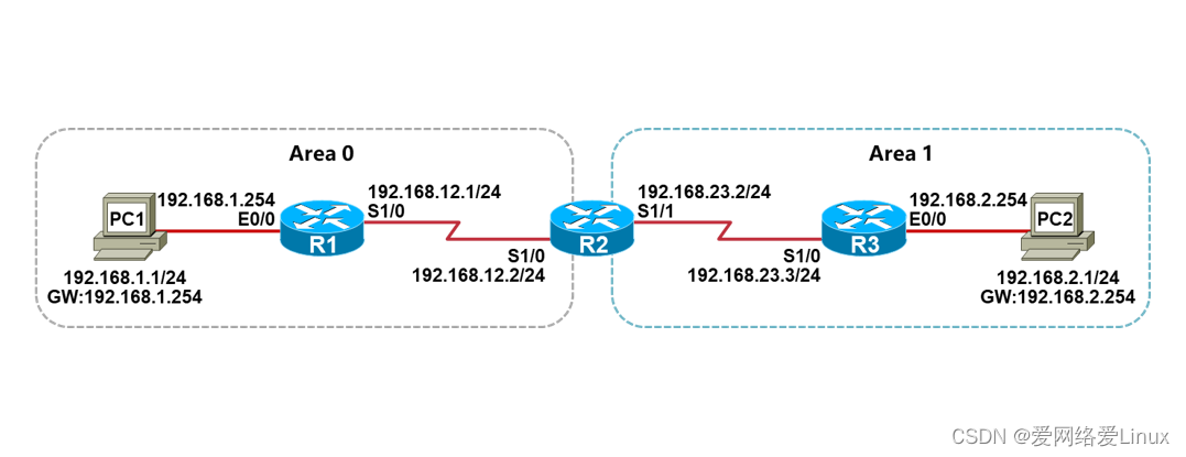
实验需求
- 根据实验拓扑图,完成设备的基本配置;
- 分别在R1、R2、R3上创建Loopback0接口,IP地址分别是1.1.1.1/32、2.2.2/32、3.3.3.3/32,Loopback0地址作为OSPF的Router-ID;
- 根据实验拓扑图的区域划分,在R1、R2、R3上配置OSPF,使得全网路由可达。
实验步骤
步骤1:设备的基本配置
配置PC1:
VPCS> set pcname PC1 //设置主机名
PC1> ip 192.168.1.1/24 192.168.1.254 //设置IP地址与网关
配置PC2:
VPCS> set pcname PC2
PC2> ip 192.168.2.1/24 192.168.2.254
配置R1:
Router>enable
Router#configure terminal
Router(config)#hostname R1
R1(config)#no ip domain-lookup
R1(config)#line console 0
R1(config-line)#exec-timeout 0 0
R1(config-line)#logging synchronous
R1(config-line)#exit
R1(config)#interface loopback0
R1(config-if)#ip address 1.1.1.1 255.255.255.255
R1(config-if)#exit
R1(config)#interface ethernet0/0
R1(config-if)#ip address 192.168.1.254 255.255.255.0
R1(config-if)#no shutdown
R1(config-if)#exit
R1(config)#interface serial1/0
R1(config-if)#ip address 192.168.12.1 255.255.255.0
R1(config-if)#no shutdown
R1(config-if)#end
R1#
配置R2:
Router>enable
Router#configure terminal
Router(config)#hostname R2
R2(config)#no ip domain-lookup
R2(config)#line console 0
R2(config-line)#exec-timeout 0 0
R2(config-line)#logging synchronous
R2(config-line)#exit
R2(config)#interface loopback0
R2(config-if)#ip address 2.2.2.2 255.255.255.255
R2(config-if)#exit
R2(config)#interface serial1/0
R2(config-if)#ip address 192.168.12.2 255.255.255.0
R2(config-if)#no shutdown
R2(config-if)#exit
R2(config)#interface serial1/1
R2(config-if)#ip address 192.168.23.2 255.255.255.0
R2(config-if)#no shutdown
R2(config-if)#end
R2#
配置R3:
Router>enable
Router#configure terminal
Router(config)#hostname R3
R3(config)#no ip domain-lookup
R3(config)#line console 0
R3(config-line)#exec-timeout 0 0
R3(config-line)#logging synchronous
R3(config-line)#exit
R3(config)#interface loopback0
R3(config-if)#ip address 3.3.3.3 255.255.255.255
R3(config-if)#exit
R3(config)#interface ethernet0/0
R3(config-if)#ip address 192.168.2.254 255.255.255.0
R3(config-if)#no shutdown
R3(config-if)#exit
R3(config)#interface serial1/0
R3(config-if)#ip address 192.168.23.3 255.255.255.0
R3(config-if)#no shutdown
R3(config-if)#end
R3#
步骤2:检查设备接口状态
检查PC1:
PC1> show ip
NAME : PC1[1]
IP/MASK : 192.168.1.1/24
GATEWAY : 192.168.1.254
DNS :
MAC : 00:50:79:66:68:04
LPORT : 20000
RHOST:PORT : 127.0.0.1:30000
MTU : 1500
检查R1:
R1#show ip interface brief
Interface IP-Address OK? Method Status Protocol
Ethernet0/0 192.168.1.254 YES manual up up
Ethernet0/1 unassigned YES unset administratively down down
Ethernet0/2 unassigned YES unset administratively down down
Ethernet0/3 unassigned YES unset administratively down down
Serial1/0 192.168.12.1 YES manual up up
Serial1/1 unassigned YES unset administratively down down
Serial1/2 unassigned YES unset administratively down down
Serial1/3 unassigned YES unset administratively down down
Loopback0 1.1.1.1 YES manual up up
检查R2:
R2#show ip interface brief
Interface IP-Address OK? Method Status Protocol
Ethernet0/0 unassigned YES unset administratively down down
Ethernet0/1 unassigned YES unset administratively down down
Ethernet0/2 unassigned YES unset administratively down down
Ethernet0/3 unassigned YES unset administratively down down
Serial1/0 192.168.12.2 YES manual up up
Serial1/1 192.168.23.2 YES manual up up
Serial1/2 unassigned YES unset administratively down down
Serial1/3 unassigned YES unset administratively down down
Loopback0 2.2.2.2 YES manual up up
检查R3:
R3#show ip interface brief
Interface IP-Address OK? Method Status Protocol
Ethernet0/0 192.168.2.254 YES manual up up
Ethernet0/1 unassigned YES unset administratively down down
Ethernet0/2 unassigned YES unset administratively down down
Ethernet0/3 unassigned YES unset administratively down down
Serial1/0 192.168.23.3 YES manual up up
Serial1/1 unassigned YES unset administratively down down
Serial1/2 unassigned YES unset administratively down down
Serial1/3 unassigned YES unset administratively down down
Loopback0 3.3.3.3 YES manual up up
检查PC2:
PC2> show ip
NAME : PC2[1]
IP/MASK : 192.168.2.1/24
GATEWAY : 192.168.2.254
DNS :
MAC : 00:50:79:66:68:05
LPORT : 20000
RHOST:PORT : 127.0.0.1:30000
MTU : 1500
步骤3:测试直连网络的连通性
测试PC1跟网关的网络连通性:
PC1> ping 192.168.1.254
84 bytes from 192.168.1.254 icmp_seq=1 ttl=255 time=0.359 ms
84 bytes from 192.168.1.254 icmp_seq=2 ttl=255 time=0.459 ms
84 bytes from 192.168.1.254 icmp_seq=3 ttl=255 time=0.463 ms
84 bytes from 192.168.1.254 icmp_seq=4 ttl=255 time=0.403 ms
84 bytes from 192.168.1.254 icmp_seq=5 ttl=255 time=0.417 ms
测试R1跟R2之间的网络连通性:
R1#ping 192.168.12.2
Type escape sequence to abort.
Sending 5, 100-byte ICMP Echos to 192.168.12.2, timeout is 2 seconds:
!!!!!
Success rate is 100 percent (5/5), round-trip min/avg/max = 8/9/10 ms
测试R2跟R3之间的网络连通性:
R2#ping 192.168.23.3
Type escape sequence to abort.
Sending 5, 100-byte ICMP Echos to 192.168.23.3, timeout is 2 seconds:
!!!!!
Success rate is 100 percent (5/5), round-trip min/avg/max = 9/9/11 ms
测试PC2跟网关的网络连通性:
PC2> ping 192.168.2.254
84 bytes from 192.168.2.254 icmp_seq=1 ttl=255 time=0.469 ms
84 bytes from 192.168.2.254 icmp_seq=2 ttl=255 time=0.484 ms
84 bytes from 192.168.2.254 icmp_seq=3 ttl=255 time=0.518 ms
84 bytes from 192.168.2.254 icmp_seq=4 ttl=255 time=0.400 ms
- ytes from 192.168.2.254 icmp_seq=5 ttl=255 time=0.405 ms
步骤4:配置OSPF
配置R1:
R1(config)#router ospf 1
R1(config-router)#router-id 1.1.1.1
R1(config-router)#network 192.168.1.0 0.0.0.255 area 0
R1(config-router)#network 192.168.12.0 0.0.0.255 area 0
R1(config-router)#end
R1#
配置R2:
R2(config)#router ospf 1
R2(config-router)#router-id 2.2.2.2
R2(config-router)#network 192.168.12.0 0.0.0.255 area 0
R2(config-router)#network 192.168.23.0 0.0.0.255 area 1
R2(config-router)#end
R2#
配置R3:
R3(config)#router ospf 1
R3(config-router)#router-id 3.3.3.3
R3(config-router)#network 192.168.23.0 0.0.0.255 area 1
R3(config-router)#network 192.168.2.0 0.0.0.255 area 1
R3(config-router)#end
R3#
实验检查
步骤1:检查OSPF邻居
检查R1:
R1#show ip ospf neighbor
Neighbor ID Pri State Dead Time Address Interface
2.2.2.2 0 FULL/ - 00:00:31 192.168.12.2 Serial1/0
Full是完全邻接状态,是正常的状态。
检查R2:
R2#show ip ospf neighbor
Neighbor ID Pri State Dead Time Address Interface
1.1.1.1 0 FULL/ - 00:00:31 192.168.12.1 Serial1/0
3.3.3.3 0 FULL/ - 00:00:39 192.168.23.3 Serial1/1
检查R3:
R3#show ip ospf neighbor
Neighbor ID Pri State Dead Time Address Interface
-
-
-
- 0 FULL/ - 00:00:33 192.168.23.2 Serial1/0
-
-
步骤2:检查OSPF路由
检查R1:
R1#show ip route
Codes: L - local, C - connected, S - static, R - RIP, M - mobile, B - BGP
D - EIGRP, EX - EIGRP external, O - OSPF, IA - OSPF inter area
N1 - OSPF NSSA external type 1, N2 - OSPF NSSA external type 2
E1 - OSPF external type 1, E2 - OSPF external type 2
i - IS-IS, su - IS-IS summary, L1 - IS-IS level-1, L2 - IS-IS level-2
ia - IS-IS inter area, * - candidate default, U - per-user static route
o - ODR, P - periodic downloaded static route, H - NHRP, l - LISP
a - application route
+ - replicated route, % - next hop override, p - overrides from PfR
Gateway of last resort is not set
1.0.0.0/32 is subnetted, 1 subnets
C 1.1.1.1 is directly connected, Loopback0
192.168.1.0/24 is variably subnetted, 2 subnets, 2 masks
C 192.168.1.0/24 is directly connected, Ethernet0/0
L 192.168.1.254/32 is directly connected, Ethernet0/0
O IA 192.168.2.0/24 [110/138] via 192.168.12.2, 00:04:48, Serial1/0
192.168.12.0/24 is variably subnetted, 2 subnets, 2 masks
C 192.168.12.0/24 is directly connected, Serial1/0
L 192.168.12.1/32 is directly connected, Serial1/0
O IA 192.168.23.0/24 [110/128] via 192.168.12.2, 00:06:10, Serial1/0
R1有两条O IA的路由,O IA表示OSPF区域间的路由;
因为R1所有接口都是属于Area 0,192.168.2.0/24和192.168.23.0/24都是属于Area 1,所以通过R2跨区域传递给R1之后,就形成了O IA路由。
检查R2:
R2#show ip route
Codes: L - local, C - connected, S - static, R - RIP, M - mobile, B - BGP
D - EIGRP, EX - EIGRP external, O - OSPF, IA - OSPF inter area
N1 - OSPF NSSA external type 1, N2 - OSPF NSSA external type 2
E1 - OSPF external type 1, E2 - OSPF external type 2
i - IS-IS, su - IS-IS summary, L1 - IS-IS level-1, L2 - IS-IS level-2
ia - IS-IS inter area, * - candidate default, U - per-user static route
o - ODR, P - periodic downloaded static route, H - NHRP, l - LISP
a - application route
+ - replicated route, % - next hop override, p - overrides from PfR
Gateway of last resort is not set
2.0.0.0/32 is subnetted, 1 subnets
C 2.2.2.2 is directly connected, Loopback0
O 192.168.1.0/24 [110/74] via 192.168.12.1, 00:09:55, Serial1/0
O 192.168.2.0/24 [110/74] via 192.168.23.3, 00:08:24, Serial1/1
192.168.12.0/24 is variably subnetted, 2 subnets, 2 masks
C 192.168.12.0/24 is directly connected, Serial1/0
L 192.168.12.2/32 is directly connected, Serial1/0
192.168.23.0/24 is variably subnetted, 2 subnets, 2 masks
C 192.168.23.0/24 is directly connected, Serial1/1
L 192.168.23.2/32 is directly connected, Serial1/1
因为R1既有接口属于Area 0,也有接口属于Area 1;
所以R1的路由表看到的都是O路由,O表示OSPF区域内的路由。
实验15:配置标准ACL
实验目的
-
- 理解标准ACL的应用
- 掌握标准ACL的配置
实验拓扑
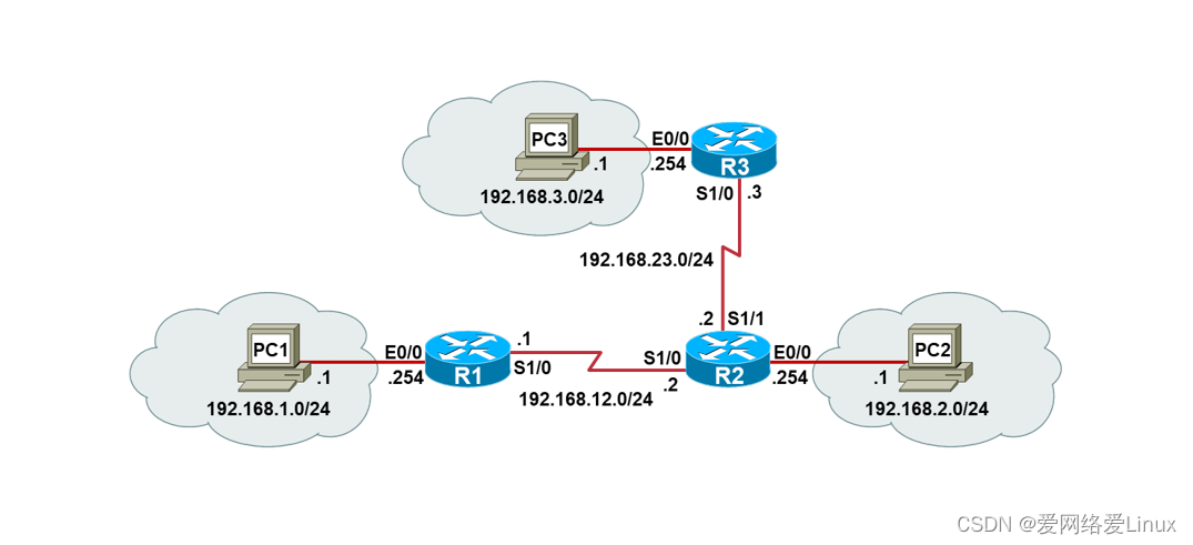
实验需求
- 根据实验拓扑图,完成设备的基本配置;
- 配置静态路由,使得全网路由可达;
- 在R3上部署ACL,只允许192.168.1.0/24和192.168.2.0/24网段的用户访问PC3。
实验步骤
步骤1:设备的基本配置
配置PC1:
Router>enable
Router#configure terminal
Router(config)#hostname PC1
PC1(config)#no ip routing
PC1(config)#ip default-gateway 192.168.1.254
PC1(config)#interface ethernet0/0
PC1(config-if)#ip address 192.168.1.1 255.255.255.0
PC1(config-if)#no shutdown
PC1(config-if)#end
PC1#
配置PC2:
Router>enable
Router#configure terminal
Router(config)#hostname PC2
PC2(config)#no ip routing
PC2(config)#ip default-gateway 192.168.2.254
PC2(config)#interface ethernet0/0
PC2(config-if)#ip address 192.168.2.1 255.255.255.0
PC2(config-if)#no shutdown
PC2(config-if)#end
PC2#
配置PC3:
Router>enable
Router#configure terminal
Router(config)#hostname PC3
PC3(config)#no ip routing
PC3(config)#ip default-gateway 192.168.3.254
PC3(config)#interface ethernet0/0
PC3(config-if)#ip address 192.168.3.1 255.255.255.0
PC3(config-if)#no shutdown
PC3(config-if)#end
PC3#
配置R1:
Router>enable
Router#configure terminal
Router(config)#hostname R1
R1(config)#no ip domain-lookup
R1(config)#line console 0
R1(config-line)#exec-timeout 0 0
R1(config-line)#logging synchronous
R1(config-line)#exit
R1(config)#interface ethernet0/0
R1(config-if)#ip address 192.168.1.254 255.255.255.0
R1(config-if)#no shutdown
R1(config-if)#exit
R1(config)#interface serial1/0
R1(config-if)#ip address 192.168.12.1 255.255.255.0
R1(config-if)#no shutdown
R1(config-if)#end
R1#
配置R2:
Router>enable
Router#configure terminal
Router(config)#hostname R2
R2(config)#no ip domain-lookup
R2(config)#line console 0
R2(config-line)#exec-timeout 0 0
R2(config-line)#logging synchronous
R2(config-line)#exit
R2(config)#interface serial1/0
R2(config-if)#ip address 192.168.12.2 255.255.255.0
R2(config-if)#no shutdown
R2(config-if)#exit
R2(config)#interface serial1/1
R2(config-if)#ip address 192.168.23.2 255.255.255.0
R2(config-if)#no shutdown
R2(config-if)#exit
R2(config)#interface ethernet0/0
R2(config-if)#ip address 192.168.2.254 255.255.255.0
R2(config-if)#no shutdown
R2(config-if)#end
R2#
配置R3:
Router>enable
Router#configure terminal
Router(config)#hostname R3
R3(config)#no ip domain-lookup
R3(config)#line console 0
R3(config-line)#exec-timeout 0 0
R3(config-line)#logging synchronous
R3(config-line)#exit
R3(config)#interface ethernet0/0
R3(config-if)#ip address 192.168.3.254 255.255.255.0
R3(config-if)#no shutdown
R3(config-if)#exit
R3(config)#interface serial1/0
R3(config-if)#ip address 192.168.23.3 255.255.255.0
R3(config-if)#no shutdown
R3(config-if)#end
R3#
步骤2:配置静态路由
配置R1:
R1(config)#ip route 192.168.2.0 255.255.255.0 192.168.12.2
R1(config)#ip route 192.168.3.0 255.255.255.0 192.168.12.2
R1(config)#ip route 192.168.23.0 255.255.255.0 192.168.12.2
配置R2:
R2(config)#ip route 192.168.1.0 255.255.255.0 serial1/0
R2(config)#ip route 192.168.3.0 255.255.255.0 serial1/1
配置R3:
R3(config)#ip route 192.168.1.0 255.255.255.0 192.168.23.2
R3(config)#ip route 192.168.2.0 255.255.255.0 192.168.23.2
R3(config)#ip route 192.168.12.0 255.255.255.0 192.168.23.2
这个时候任何一个网段都能访问PC3。
测试PC1访问PC3:
PC1#ping 192.168.3.1
Type escape sequence to abort.
Sending 5, 100-byte ICMP Echos to 192.168.3.1, timeout is 2 seconds:
!!!!!
Success rate is 100 percent (5/5), round-trip min/avg/max = 19/20/22 ms
测试PC2访问PC3:
PC2#ping 192.168.3.1
Type escape sequence to abort.
Sending 5, 100-byte ICMP Echos to 192.168.3.1, timeout is 2 seconds:
!!!!!
Success rate is 100 percent (5/5), round-trip min/avg/max = 10/10/11 ms
测试R1访问PC3:
R1#ping 192.168.3.1
Type escape sequence to abort.
Sending 5, 100-byte ICMP Echos to 192.168.3.1, timeout is 2 seconds:
!!!!!
Success rate is 100 percent (5/5), round-trip min/avg/max = 16/19/22 ms
步骤3:配置标准ACL
配置R3
R3(config)#access-list 1 permit 192.168.1.0 0.0.0.255
R3(config)#access-list 1 permit 192.168.2.0 0.0.0.255
R3(config)#interface serial1/0
R3(config-if)#ip access-group 1 in
R3(config-if)#end
R3#
这个时候除了192.168.1.0/24和192.168.2.0/24网段,其他网段就访问不了了。
测试PC1访问PC3:
PC1#ping 192.168.3.1
Type escape sequence to abort.
Sending 5, 100-byte ICMP Echos to 192.168.3.1, timeout is 2 seconds:
!!!!!
Success rate is 100 percent (5/5), round-trip min/avg/max = 19/20/22 ms
测试PC2访问PC3:
PC2#ping 192.168.3.1
Type escape sequence to abort.
Sending 5, 100-byte ICMP Echos to 192.168.3.1, timeout is 2 seconds:
!!!!!
Success rate is 100 percent (5/5), round-trip min/avg/max = 10/10/11 ms
测试R1访问PC3:
R1#ping 192.168.3.1
Type escape sequence to abort.
Sending 5, 100-byte ICMP Echos to 192.168.3.1, timeout is 2 seconds:
U.U.U
Success rate is 0 percent (0/5)
被ACL拒绝了。
实验16:配置扩展ACL
实验目的
- 理解扩展ACL的应用
- 掌握扩展ACL的配置
实验拓扑

实验需求
- 根据实验拓扑图,完成设备的基本配置;
- 配置EIGRP,使得全网路由可达;
- 在R3上部署ACL,只允许192.168.1.0/24网段的用户Ping PC3;
- 在R3上部署ACL,只允许192.168.2.0/24网段的用户Telnet PC3。
实验步骤
步骤1:设备的基本配置
配置PC1:
Router>enable
Router#configure terminal
Router(config)#hostname PC1
PC1(config)#no ip routing
PC1(config)#ip default-gateway 192.168.1.254
PC1(config)#interface ethernet0/0
PC1(config-if)#ip address 192.168.1.1 255.255.255.0
PC1(config-if)#no shutdown
PC1(config-if)#end
PC1#
配置PC2:
Router>enable
Router#configure terminal
Router(config)#hostname PC2
PC2(config)#no ip routing
PC2(config)#ip default-gateway 192.168.2.254
PC2(config)#interface ethernet0/0
PC2(config-if)#ip address 192.168.2.1 255.255.255.0
PC2(config-if)#no shutdown
PC2(config-if)#end
PC2#
配置PC3:
Router>enable
Router#configure terminal
Router(config)#hostname PC3
PC3(config)#no ip routing
PC3(config)#line vty 0 4
PC3(config-line)#password xmws
PC3(config-line)#login
PC3(config-line)#transport input telnet
PC3(config-line)#exit
PC3(config)#ip default-gateway 192.168.3.254
PC3(config)#interface ethernet0/0
PC3(config-if)#ip address 192.168.3.1 255.255.255.0
PC3(config-if)#no shutdown
PC3(config-if)#end
PC3#
配置R1:
Router>enable
Router#configure terminal
Router(config)#hostname R1
R1(config)#no ip domain-lookup
R1(config)#line console 0
R1(config-line)#exec-timeout 0 0
R1(config-line)#logging synchronous
R1(config-line)#exit
R1(config)#interface ethernet0/0
R1(config-if)#ip address 192.168.1.254 255.255.255.0
R1(config-if)#no shutdown
R1(config-if)#exit
R1(config)#interface serial1/0
R1(config-if)#ip address 192.168.12.1 255.255.255.0
R1(config-if)#no shutdown
R1(config-if)#end
R1#
配置R2:
Router>enable
Router#configure terminal
Router(config)#hostname R2
R2(config)#no ip domain-lookup
R2(config)#line console 0
R2(config-line)#exec-timeout 0 0
R2(config-line)#logging synchronous
R2(config-line)#exit
R2(config)#interface serial1/0
R2(config-if)#ip address 192.168.12.2 255.255.255.0
R2(config-if)#no shutdown
R2(config-if)#exit
R2(config)#interface serial1/1
R2(config-if)#ip address 192.168.23.2 255.255.255.0
R2(config-if)#no shutdown
R2(config-if)#exit
R2(config)#interface ethernet0/0
R2(config-if)#ip address 192.168.2.254 255.255.255.0
R2(config-if)#no shutdown
R2(config-if)#end
R2#
配置R3:
Router>enable
Router#configure terminal
Router(config)#hostname R3
R3(config)#no ip domain-lookup
R3(config)#line console 0
R3(config-line)#exec-timeout 0 0
R3(config-line)#logging synchronous
R3(config-line)#exit
R3(config)#interface ethernet0/0
R3(config-if)#ip address 192.168.3.254 255.255.255.0
R3(config-if)#no shutdown
R3(config-if)#exit
R3(config)#interface serial1/0
R3(config-if)#ip address 192.168.23.3 255.255.255.0
R3(config-if)#no shutdown
R3(config-if)#end
R3#
步骤2:配置静态路由
配置R1:
R1(config)#ip route 192.168.2.0 255.255.255.0 192.168.12.2
R1(config)#ip route 192.168.3.0 255.255.255.0 192.168.12.2
R1(config)#ip route 192.168.23.0 255.255.255.0 192.168.12.2
配置R2:
R2(config)#ip route 192.168.1.0 255.255.255.0 serial1/0
R2(config)#ip route 192.168.3.0 255.255.255.0 serial1/1
配置R3:
R3(config)#ip route 192.168.1.0 255.255.255.0 192.168.23.2
R3(config)#ip route 192.168.2.0 255.255.255.0 192.168.23.2
R3(config)#ip route 192.168.12.0 255.255.255.0 192.168.23.2
这个时候任何一个网段都能访问PC3。
测试PC1 ping PC3:
PC1#ping 192.168.3.1
Type escape sequence to abort.
Sending 5, 100-byte ICMP Echos to 192.168.3.1, timeout is 2 seconds:
!!!!!
Success rate is 100 percent (5/5), round-trip min/avg/max = 19/20/22 ms
测试PC1 telnet PC3:
PC1#telnet 192.168.3.1
Trying 192.168.3.1 ... Open
User Access Verification
Password:
PC3>
测试PC2 ping PC3:
PC2#ping 192.168.3.1
Type escape sequence to abort.
Sending 5, 100-byte ICMP Echos to 192.168.3.1, timeout is 2 seconds:
!!!!!
Success rate is 100 percent (5/5), round-trip min/avg/max = 10/10/11 ms
测试PC2 telnet PC3:
PC1#telnet 192.168.3.1
Trying 192.168.3.1 ... Open
User Access Verification
Password:
PC3>
步骤3:配置扩展ACL
配置R3:
R3(config)#access-list 101 permit icmp 192.168.1.0 0.0.0.255 host 192.168.3.1
R3(config)#access-list 101 permit tcp 192.168.2.0 0.0.0.255 host 192.168.3.1 eq 23
R3(config)#interface serial 1/0
R3(config-if)#ip access-group 101 in
R3(config-if)#end
R3#
这个时候只有PC1能Ping PC3,PC2能Telnet PC3。
测试PC1 ping PC3:
PC1#ping 192.168.3.1
Type escape sequence to abort.
Sending 5, 100-byte ICMP Echos to 192.168.3.1, timeout is 2 seconds:
!!!!!
Success rate is 100 percent (5/5), round-trip min/avg/max = 19/20/22 ms
测试PC1 telnet PC3:
PC1#telnet 192.168.3.1
Trying 192.168.3.1 ...
% Destination unreachable; gateway or host down
PC1#
测试PC2 ping PC3:
PC2#ping 192.168.3.1
Type escape sequence to abort.
Sending 5, 100-byte ICMP Echos to 192.168.3.1, timeout is 2 seconds:
U.U.U
Success rate is 0 percent (0/5)
测试PC2 telnet PC3:
PC1#telnet 192.168.3.1
Trying 192.168.3.1 ... Open
User Access Verification
Password:
PC3>
实验17:配置静态NAT
实验目的
- 理解静态NAT的转换原理
- 掌握静态NAT的配置方法
实验拓扑

实验需求
- 根据实验拓扑图,完成设备的基本配置;
- 在R2上创建Loopback0接口,IP地址是9.6.7/32,模拟公网上的一台服务器;
- 在R1上配置静态NAT,PC1访问服务器使用12.1.1.11转换源地址;
- 在R1上配置静态NAT,PC2访问服务器使用12.1.1.12转换源地址。
实验步骤
步骤1:设备的基本配置
配置PC1:
Router>enable
Router#configure terminal
Router(config)#hostname PC1
PC1(config)#no ip routing
PC1(config)#ip default-gateway 192.168.1.254
PC1(config)#interface ethernet0/0
PC1(config-if)#ip address 192.168.1.1 255.255.255.0
PC1(config-if)#no shutdown
PC1(config-if)#end
PC1#
配置PC2:
Router>enable
Router#configure terminal
Router(config)#hostname PC2
PC2(config)#no ip routing
PC2(config)#ip default-gateway 192.168.1.254
PC2(config)#interface ethernet0/0
PC2(config-if)#ip address 192.168.1.2 255.255.255.0
PC2(config-if)#no shutdown
PC2(config-if)#end
PC2#
配置SW1:
Switch>ena
Switch#conf t
Switch(config)#no ip domain-lookup
Switch(config)#line console 0
Switch(config-line)# logging s
Switch(config-line)# exec-t 0 0
Switch(config-line)# exit
Switch(config)#hostname SW1
SW1(config)#end
SW1#
配置R1:
Router>enable
Router#configure terminal
Router(config)#hostname R1
R1(config)#no ip domain-lookup
R1(config)#line console 0
R1(config-line)#exec-timeout 0 0
R1(config-line)#logging synchronous
R1(config-line)#exit
R1(config)#interface ethernet0/0
R1(config-if)#ip address 192.168.1.254 255.255.255.0
R1(config-if)#no shutdown
R1(config-if)#exit
R1(config)#interface ethernet0/1
R1(config-if)#ip address 12.1.1.1 255.255.255.0
R1(config-if)#no shutdown
R1(config-if)#end
R1#
配置R2:
Router>enable
Router#configure terminal
Router(config)#hostname R2
R2(config)#no ip domain-lookup
R2(config)#line console 0
R2(config-line)#exec-timeout 0 0
R2(config-line)#logging synchronous
R2(config-line)#exit
R2(config)#interface loopback0
R2(config-if)#ip address 9.2.6.7 255.255.255.255
R2(config-if)#exit
R2(config)#interface ethernet0/0
R2(config-if)#ip address 12.1.1.2 255.255.255.0
R2(config-if)#no shutdown
R2(config-if)#end
R2#
步骤2:配置静态NAT
配置R1:
R1(config)#ip nat inside source static 192.168.1.1 12.1.1.11 //配置静态转换
R1(config)#ip nat inside source static 192.168.1.2 12.1.1.12 //配置静态转换
R1(config)#interface ethernet 0/0
R1(config-if)#ip nat inside //指定inside接口
R1(config-if)#exit
R1(config)#interface ethernet 0/1
R1(config-if)#ip nat outside //指定outside接口
R1(config-if)#exit
R1(config)#ip route 0.0.0.0 0.0.0.0 12.1.1.2 //配置到达公网的默认路由
R1(config)#end
R1#
检查R1的NAT表项:
R1#show ip nat translations
Pro Inside global Inside local Outside local Outside global
--- 12.1.1.11 192.168.1.1 --- ---
--- 12.1.1.12 192.168.1.2 --- ---
R1的NAT映射表创建了两个静态NAT条目。
测试PC1访问服务器:
PC1#ping 9.2.6.7
Type escape sequence to abort.
Sending 5, 100-byte ICMP Echos to 9.2.6.7, timeout is 2 seconds:
!!!!!
Success rate is 100 percent (5/5), round-trip min/avg/max = 1/1/1 ms
测试PC2访问服务器:
PC2#ping 9.2.6.7
Type escape sequence to abort.
Sending 5, 100-byte ICMP Echos to 9.2.6.7, timeout is 2 seconds:
!!!!!
Success rate is 100 percent (5/5), round-trip min/avg/max = 1/1/1 ms
检查R1的NAT表项:
R1#sh ip nat translations
Pro Inside global Inside local Outside local Outside global
icmp 12.1.1.11:4 192.168.1.1:4 9.2.6.7:4 9.2.6.7:4
--- 12.1.1.11 192.168.1.1 --- ---
icmp 12.1.1.12:2 192.168.1.2:2 9.2.6.7:2 9.2.6.7:2
--- 12.1.1.12 192.168.1.2 --- ---
实验18:配置动态NAT
实验目的
- 理解动态NAT的转换原理
- 掌握动态NAT的配置方法
实验拓扑
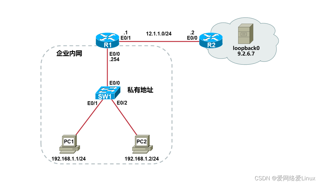
实验需求
- 根据实验拓扑图,完成设备的基本配置;
- 在R2上创建Loopback0接口,IP地址是9.6.7/32,模拟公网上的一台服务器;
- 在R1上配置动态NAT,地址池范围为12.1.1.11~12.1.1.20,使得PC1和PC2能够访问公网服务器。
实验步骤
步骤1:设备的基本配置
配置PC1:
Router>enable
Router#configure terminal
Router(config)#hostname PC1
PC1(config)#no ip routing
PC1(config)#ip default-gateway 192.168.1.254
PC1(config)#interface ethernet0/0
PC1(config-if)#ip address 192.168.1.1 255.255.255.0
PC1(config-if)#no shutdown
PC1(config-if)#end
PC1#
配置PC2:
Router>enable
Router#configure terminal
Router(config)#hostname PC2
PC2(config)#no ip routing
PC2(config)#ip default-gateway 192.168.1.254
PC2(config)#interface ethernet0/0
PC2(config-if)#ip address 192.168.1.2 255.255.255.0
PC2(config-if)#no shutdown
PC2(config-if)#end
PC2#
配置SW1:
Switch>ena
Switch#conf t
Switch(config)#no ip domain-lookup
Switch(config)#line console 0
Switch(config-line)# logging s
Switch(config-line)# exec-t 0 0
Switch(config-line)# exit
Switch(config)#hostname SW1
SW1(config)#end
SW1#
配置R1:
Router>enable
Router#configure terminal
Router(config)#hostname R1
R1(config)#no ip domain-lookup
R1(config)#line console 0
R1(config-line)#exec-timeout 0 0
R1(config-line)#logging synchronous
R1(config-line)#exit
R1(config)#interface ethernet0/0
R1(config-if)#ip address 192.168.1.254 255.255.255.0
R1(config-if)#no shutdown
R1(config-if)#exit
R1(config)#interface ethernet0/1
R1(config-if)#ip address 12.1.1.1 255.255.255.0
R1(config-if)#no shutdown
R1(config-if)#end
R1#
配置R2:
Router>enable
Router#configure terminal
Router(config)#hostname R2
R2(config)#no ip domain-lookup
R2(config)#line console 0
R2(config-line)#exec-timeout 0 0
R2(config-line)#logging synchronous
R2(config-line)#exit
R2(config)#interface loopback0
R2(config-if)#ip address 9.2.6.7 255.255.255.255
R2(config-if)#exit
R2(config)#interface ethernet0/0
R2(config-if)#ip address 12.1.1.2 255.255.255.0
R2(config-if)#no shutdown
R2(config-if)#end
R2#
步骤2:配置动态NAT
配置R1:
R1(config)#ip nat pool xmws 12.1.1.11 12.1.1.20 netmask 255.255.255.0 //创建地址池
R1(config)#access-list 1 permit 192.168.1.0 0.0.0.255 //通过ACL定义哪些子网能做NAT
R1(config)#ip nat inside source list 1 pool xmws //关联ALC和地址池
R1(config)#interface ethernet 0/0
R1(config-if)#ip nat inside //指定inside接口
R1(config-if)#exit
R1(config)#interface ethernet 0/1
R1(config-if)#ip nat outside //指定outside接口
R1(config-if)#exit
R1(config)#ip route 0.0.0.0 0.0.0.0 12.1.1.2 //配置到达公网的默认路由
测试PC1访问服务器:
PC1#ping 9.2.6.7
Type escape sequence to abort.
Sending 5, 100-byte ICMP Echos to 9.2.6.7, timeout is 2 seconds:
!!!!!
Success rate is 100 percent (5/5), round-trip min/avg/max = 1/1/1 ms
测试PC2访问服务器:
PC2#ping 9.2.6.7
Type escape sequence to abort.
Sending 5, 100-byte ICMP Echos to 9.2.6.7, timeout is 2 seconds:
!!!!!
Success rate is 100 percent (5/5), round-trip min/avg/max = 1/1/1 ms
检查R1的NAT表项:
R1#show ip nat translations
Pro Inside global Inside local Outside local Outside global
icmp 12.1.1.12:6 192.168.1.1:6 9.2.6.7:6 9.2.6.7:6
--- 12.1.1.12 192.168.1.1 --- ---
icmp 12.1.1.13:4 192.168.1.2:4 9.2.6.7:4 9.2.6.7:4
--- 12.1.1.13 192.168.1.2 --- ---
实验19:配置PAT
实验目的
- 理解PAT的转换原理
- 掌握PAT的配置方法
实验拓扑
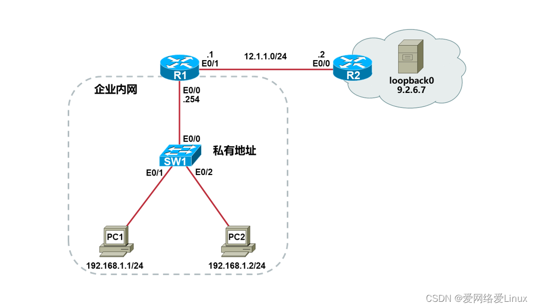
实验需求
- 根据实验拓扑图,完成设备的基本配置;
- 在R2上创建Loopback0接口,IP地址是9.6.7/32,模拟公网上的一台服务器;
- 在R1上配置PAT,使得PC1和PC2能够复用E0/1接口地址访问公网服务器。
实验步骤
步骤1:设备的基本配置
配置PC1:
Router>enable
Router#configure terminal
Router(config)#hostname PC1
PC1(config)#no ip routing
PC1(config)#ip default-gateway 192.168.1.254
PC1(config)#interface ethernet0/0
PC1(config-if)#ip address 192.168.1.1 255.255.255.0
PC1(config-if)#no shutdown
PC1(config-if)#end
PC1#
配置PC2:
Router>enable
Router#configure terminal
Router(config)#hostname PC2
PC2(config)#no ip routing
PC2(config)#ip default-gateway 192.168.1.254
PC2(config)#interface ethernet0/0
PC2(config-if)#ip address 192.168.1.2 255.255.255.0
PC2(config-if)#no shutdown
PC2(config-if)#end
PC2#
配置SW1:
Switch>ena
Switch#conf t
Switch(config)#no ip domain-lookup
Switch(config)#line console 0
Switch(config-line)# logging s
Switch(config-line)# exec-t 0 0
Switch(config-line)# exit
Switch(config)#hostname SW1
SW1(config)#end
SW1#
配置R1:
Router>enable
Router#configure terminal
Router(config)#hostname R1
R1(config)#no ip domain-lookup
R1(config)#line console 0
R1(config-line)#exec-timeout 0 0
R1(config-line)#logging synchronous
R1(config-line)#exit
R1(config)#interface ethernet0/0
R1(config-if)#ip address 192.168.1.254 255.255.255.0
R1(config-if)#no shutdown
R1(config-if)#exit
R1(config)#interface ethernet0/1
R1(config-if)#ip address 12.1.1.1 255.255.255.0
R1(config-if)#no shutdown
R1(config-if)#end
R1#
配置R2:
Router>enable
Router#configure terminal
Router(config)#hostname R2
R2(config)#no ip domain-lookup
R2(config)#line console 0
R2(config-line)#exec-timeout 0 0
R2(config-line)#logging synchronous
R2(config-line)#exit
R2(config)#interface loopback0
R2(config-if)#ip address 9.2.6.7 255.255.255.255
R2(config-if)#exit
R2(config)#interface ethernet0/0
R2(config-if)#ip address 12.1.1.2 255.255.255.0
R2(config-if)#no shutdown
R2(config-if)#end
R2#
步骤2:配置PAT
配置R1:
R1(config)#access-list 1 permit 192.168.1.0 0.0.0.255 //定义ACL
R1(config)#ip nat inside source list 1 interface ethernet 0/1 overload //关联ACL和outside接口
R1(config)#interface ethernet 0/0
R1(config-if)#ip nat inside //指定inside接口
R1(config-if)#exit
R1(config)#interface ethernet 0/1
R1(config-if)#ip nat outside //指定outside接口
R1(config-if)#exit
R1(config)#ip route 0.0.0.0 0.0.0.0 12.1.1.2 //配置到达公网的默认路由
测试PC1访问服务器:
PC1#ping 9.2.6.7
Type escape sequence to abort.
Sending 5, 100-byte ICMP Echos to 9.2.6.7, timeout is 2 seconds:
!!!!!
Success rate is 100 percent (5/5), round-trip min/avg/max = 1/1/1 ms
测试PC2访问服务器:
PC2#ping 9.2.6.7
Type escape sequence to abort.
Sending 5, 100-byte ICMP Echos to 9.2.6.7, timeout is 2 seconds:
!!!!!
Success rate is 100 percent (5/5), round-trip min/avg/max = 1/1/1 ms
检查R1的NAT表项:
R1#show ip nat translations
Pro Inside global Inside local Outside local Outside global
icmp 12.1.1.1:7 192.168.1.1:7 9.2.6.7:7 9.2.6.7:7
icmp 12.1.1.1:5 192.168.1.2:5 9.2.6.7:5 9.2.6.7:5
Inside global都是12.1.1.1,通过端口号区分不同的主机。
实验20:配置静态PAT
实验目的
- 理解静态PAT的转换原理
- 掌握静态PAT的配置方法
实验拓扑
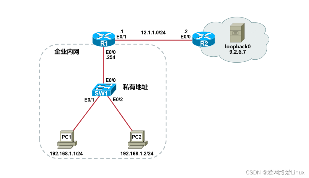
实验需求
- 根据实验拓扑图,完成设备的基本配置;
- 在R2上创建Loopback0接口,IP地址是9.6.7/32,模拟公网上的一台服务器;
- 在R1上配置静态PAT,使得Internet用户能够访问PC1的Telnet服务;
- 在R1上配置静态PAT,使得Internet用户能够访问PC2的Web服务。
实验步骤
步骤1:设备的基本配置
配置PC1:
Router>enable
Router#configure terminal
Router(config)#hostname PC1
PC1(config)#line vty 0 4 //进入VTY
PC1(config-line)#password xmws //设置VTY密码
PC1(config-line)#login //启用密码
PC1(config-line)#transport input telnet //允许Telnet远程登录
PC1(config-line)#exit
PC1(config)#no ip routing
PC1(config)#ip default-gateway 192.168.1.254
PC1(config)#interface ethernet0/0
PC1(config-if)#ip address 192.168.1.1 255.255.255.0
PC1(config-if)#no shutdown
PC1(config-if)#end
PC1#
配置PC2:
Router>enable
Router#configure terminal
Router(config)#hostname PC2
PC2(config)#no ip routing
PC2(config)#ip http server //开启HTTP服务
PC2(config)#ip default-gateway 192.168.1.254
PC2(config)#interface ethernet0/0
PC2(config-if)#ip address 192.168.1.2 255.255.255.0
PC2(config-if)#no shutdown
PC2(config-if)#end
PC2#
配置SW1:
Switch>ena
Switch#conf t
Switch(config)#no ip domain-lookup
Switch(config)#line console 0
Switch(config-line)# logging s
Switch(config-line)# exec-t 0 0
Switch(config-line)# exit
Switch(config)#hostname SW1
SW1(config)#end
SW1#
配置R1:
Router>enable
Router#configure terminal
Router(config)#hostname R1
R1(config)#no ip domain-lookup
R1(config)#line console 0
R1(config-line)#exec-timeout 0 0
R1(config-line)#logging synchronous
R1(config-line)#exit
R1(config)#interface ethernet0/0
R1(config-if)#ip address 192.168.1.254 255.255.255.0
R1(config-if)#no shutdown
R1(config-if)#exit
R1(config)#interface ethernet0/1
R1(config-if)#ip address 12.1.1.1 255.255.255.0
R1(config-if)#no shutdown
R1(config-if)#end
R1#
配置R2:
Router>enable
Router#configure terminal
Router(config)#hostname R2
R2(config)#no ip domain-lookup
R2(config)#line console 0
R2(config-line)#exec-timeout 0 0
R2(config-line)#logging synchronous
R2(config-line)#exit
R2(config)#interface loopback0
R2(config-if)#ip address 9.2.6.7 255.255.255.255
R2(config-if)#exit
R2(config)#interface ethernet0/0
R2(config-if)#ip address 12.1.1.2 255.255.255.0
R2(config-if)#no shutdown
R2(config-if)#end
R2#
步骤2:配置动态NAT
配置R1:
R1(config)#ip nat inside source static tcp 192.168.1.1 23 12.1.1.1 23 //创建静态映射
R1(config)#ip nat inside source static tcp 192.168.1.2 80 12.1.1.1 80 //创建静态映射
R1(config)#interface ethernet 0/0
R1(config-if)#ip nat inside //指定inside接口
R1(config-if)#exit
R1(config)#interface ethernet 0/1
R1(config-if)#ip nat outside //指定outside接口
R1(config-if)#exit
R1(config)#ip route 0.0.0.0 0.0.0.0 12.1.1.2 //定义到达公网的默认路由
检查R1的NAT表项:
R1#show ip nat translations
Pro Inside global Inside local Outside local Outside global
tcp 12.1.1.1:23 192.168.1.1:23 --- ---
tcp 12.1.1.1:80 192.168.1.2:80 --- ---
因为是静态PAT,所以即使没有流量,NAT转换表也有条目。
在R2上测试Telnet服务:
R2#telnet 12.1.1.1
Trying 12.1.1.1 ... Open
User Access Verification
Password:
PC1>
PC1的Telnet服务发布成功。
在R2上测试Web服务:
R2#telnet 12.1.1.1 80
Trying 12.1.1.1, 80 ... Open
PC2的Web服务发布成功。
检查R1的NAT表项:
R1#show ip nat translations
Pro Inside global Inside local Outside local Outside global
tcp 12.1.1.1:23 192.168.1.1:23 12.1.1.2:64490 12.1.1.2:64490
tcp 12.1.1.1:23 192.168.1.1:23 --- ---
tcp 12.1.1.1:80 192.168.1.2:80 12.1.1.2:36455 12.1.1.2:36455
tcp 12.1.1.1:80 192.168.1.2:80 --- ---
有流量触发之后,NAT转换表多出两个动态条目。
实验21:配置PAP单向认证
实验目的
- 理解PAP认证的原理
- 掌握PAP认证的配置
实验拓扑
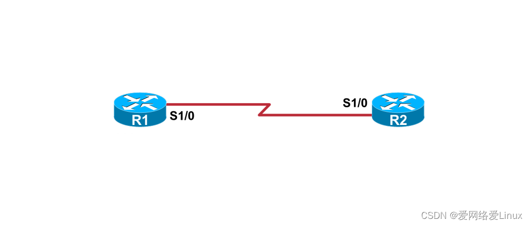
实验需求
- 根据实验拓扑图,完成设备的基本配置;
- 在R1和R2之间做PAP单向认证,R1是认证方,R2是被认证方。
实验步骤
步骤1:设备的基本配置
配置R1:
Router>enable
Router#configure terminal
Router(config)#hostname R1
R1(config)#no ip domain-lookup
R1(config)#line console 0
R1(config-line)#exec-timeout 0 0
R1(config-line)#logging synchronous
R1(config-line)#exit
R1(config)#interface serial1/0
R1(config-if)#ip address 12.1.1.1 255.255.255.0
R1(config-if)#no shutdown
R1(config-if)#end
R1#
配置R2:
Router>enable
Router#configure terminal
Router(config)#hostname R2
R2(config)#no ip domain-lookup
R2(config)#line console 0
R2(config-line)#exec-timeout 0 0
R2(config-line)#logging synchronous
R2(config-line)#exit
R2(config)#interface serial1/0
R2(config-if)#ip address 12.1.1.2 255.255.255.0
R2(config-if)#no shutdown
R2(config-if)#end
R2#
步骤2:配置PAP认证
配置R1:
R1(config)#interface serial 1/0
R1(config-if)#encapsulation ppp //封装PPP
R1(config-if)#ppp authentication pap //启用PAP认证
R1(config-if)#exit
R1(config)#username xmws password wisdom //创建用户名和密码
R1(config)#end
R1#
配置R2:
R2(config)#interface serial 1/0
R2(config-if)#encapsulation ppp //封装PPP
R2(config-if)#ppp pap sent-username xmws password wisdom //PAP发送的用户名和密码
R2(config-if)#end
R2#
步骤3:检查PAP认证
检查R1:
R1#show ip interface brief
Interface IP-Address OK? Method Status Protocol
Ethernet0/0 unassigned YES unset administratively down down
Ethernet0/1 unassigned YES unset administratively down down
Ethernet0/2 unassigned YES unset administratively down down
Ethernet0/3 unassigned YES unset administratively down down
Serial1/0 12.1.1.1 YES manual up up
Serial1/1 unassigned YES unset administratively down down
Serial1/2 unassigned YES unset administratively down down
Serial1/3 unassigned YES unset administratively down down
检查R2:
R2#show ip interface brief
Interface IP-Address OK? Method Status Protocol
Ethernet0/0 unassigned YES unset administratively down down
Ethernet0/1 unassigned YES unset administratively down down
Ethernet0/2 unassigned YES unset administratively down down
Ethernet0/3 unassigned YES unset administratively down down
Serial1/0 12.1.1.2 YES manual up up
Serial1/1 unassigned YES unset administratively down down
Serial1/2 unassigned YES unset administratively down down
Serial1/3 unassigned YES unset administratively down down
实验22:配置PAP双向认证
实验目的
- 理解PAP认证的原理
- 掌握PAP认证的配置
实验拓扑

实验需求
- 根据实验拓扑图,完成设备的基本配置;
- 在R1和R2之间做PAP的双向认证。
实验步骤
步骤1:设备的基本配置
配置R1:
Router>enable
Router#configure terminal
Router(config)#hostname R1
R1(config)#no ip domain-lookup
R1(config)#line console 0
R1(config-line)#exec-timeout 0 0
R1(config-line)#logging synchronous
R1(config-line)#exit
R1(config)#interface serial1/0
R1(config-if)#ip address 12.1.1.1 255.255.255.0
R1(config-if)#no shutdown
R1(config-if)#end
R1#
配置R2:
Router>enable
Router#configure terminal
Router(config)#hostname R2
R2(config)#no ip domain-lookup
R2(config)#line console 0
R2(config-line)#exec-timeout 0 0
R2(config-line)#logging synchronous
R2(config-line)#exit
R2(config)#interface serial1/0
R2(config-if)#ip address 12.1.1.2 255.255.255.0
R2(config-if)#no shutdown
R2(config-if)#end
R2#
步骤2:配置PAP认证
配置R1:
R1(config)#interface serial 1/0
R1(config-if)#encapsulation ppp //封装PPP
R1(config-if)#ppp authentication pap //启用PAP认证
R1(config-if)#ppp pap sent-username R1 password xmws //PAP发送的用户名和密码
R1(config-if)#exit
R1(config)#username R2 password xmws //创建用户名和密码
R1(config)#end
R1#
配置R2:
R2(config)#interface serial 1/0
R2(config-if)#encapsulation ppp //封装PPP
R2(config-if)#ppp authentication pap //启用PAP认证
R2(config-if)#ppp pap sent-username R2 password xmws //PAP发送的用户名和密码
R2(config-if)#exit
R2(config)#username R1 password xmws //创建用户名和密码
R2(config)#end
R2#
步骤3:检查PAP认证
检查R1:
R1#show ip interface brief
Interface IP-Address OK? Method Status Protocol
Ethernet0/0 unassigned YES unset administratively down down
Ethernet0/1 unassigned YES unset administratively down down
Ethernet0/2 unassigned YES unset administratively down down
Ethernet0/3 unassigned YES unset administratively down down
Serial1/0 12.1.1.1 YES manual up up
Serial1/1 unassigned YES unset administratively down down
Serial1/2 unassigned YES unset administratively down down
Serial1/3 unassigned YES unset administratively down down
检查R2:
R2#show ip interface brief
Interface IP-Address OK? Method Status Protocol
Ethernet0/0 unassigned YES unset administratively down down
Ethernet0/1 unassigned YES unset administratively down down
Ethernet0/2 unassigned YES unset administratively down down
Ethernet0/3 unassigned YES unset administratively down down
Serial1/0 12.1.1.2 YES manual up up
Serial1/1 unassigned YES unset administratively down down
Serial1/2 unassigned YES unset administratively down down
Serial1/3 unassigned YES unset administratively down down
实验23:配置CHAP单向认证
实验目的
- 理解CHAP认证的原理
- 掌握CHAP认证的配置
实验拓扑
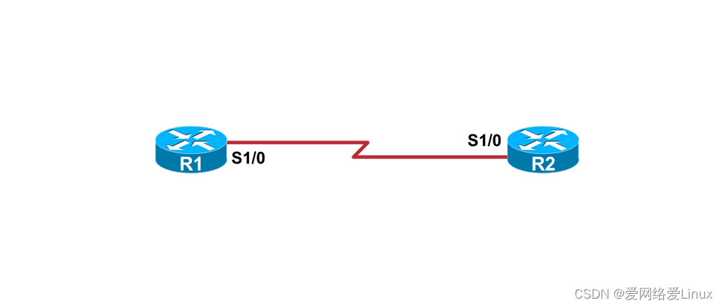
实验需求
- 根据实验拓扑图,完成设备的基本配置;
- 在R1和R2之间做CHAP单向认证,R1是认证方,R2是被认证方。
实验步骤
步骤1:设备的基本配置
配置R1:
Router>enable
Router#configure terminal
Router(config)#hostname R1
R1(config)#no ip domain-lookup
R1(config)#line console 0
R1(config-line)#exec-timeout 0 0
R1(config-line)#logging synchronous
R1(config-line)#exit
R1(config)#interface serial1/0
R1(config-if)#ip address 12.1.1.1 255.255.255.0
R1(config-if)#no shutdown
R1(config-if)#end
R1#
配置R2:
Router>enable
Router#configure terminal
Router(config)#hostname R2
R2(config)#no ip domain-lookup
R2(config)#line console 0
R2(config-line)#exec-timeout 0 0
R2(config-line)#logging synchronous
R2(config-line)#exit
R2(config)#interface serial1/0
R2(config-if)#ip address 12.1.1.2 255.255.255.0
R2(config-if)#no shutdown
R2(config-if)#end
R2#
步骤2:配置CHAP认证
配置R1:
R1(config)#interface serial 1/0
R1(config-if)#encapsulation ppp //封装PPP
R1(config-if)#ppp authentication chap //启用CHAP认证
R1(config-if)#exit
R1(config)#username xmws password wisdom //创建用户名和密码
R1(config)#end
R1#
配置R2:
R2(config)#interface serial 1/0
R2(config-if)#encapsulation ppp //封装PPP
R2(config-if)#ppp chap hostname xmws //CHAP认证的用户名
R2(config-if)#ppp chap password wisdom //CHAP认证的密码
R2(config-if)#end
R2#
步骤3:检查:CHAP认证
检查R1:
R1#show ip interface brief
Interface IP-Address OK? Method Status Protocol
Ethernet0/0 unassigned YES unset administratively down down
Ethernet0/1 unassigned YES unset administratively down down
Ethernet0/2 unassigned YES unset administratively down down
Ethernet0/3 unassigned YES unset administratively down down
Serial1/0 12.1.1.1 YES manual up up
Serial1/1 unassigned YES unset administratively down down
Serial1/2 unassigned YES unset administratively down down
Serial1/3 unassigned YES unset administratively down down
检查R2:
R2#show ip interface brief
Interface IP-Address OK? Method Status Protocol
Ethernet0/0 unassigned YES unset administratively down down
Ethernet0/1 unassigned YES unset administratively down down
Ethernet0/2 unassigned YES unset administratively down down
Ethernet0/3 unassigned YES unset administratively down down
Serial1/0 12.1.1.2 YES manual up up
Serial1/1 unassigned YES unset administratively down down
Serial1/2 unassigned YES unset administratively down down
Serial1/3 unassigned YES unset administratively down down
实验24:配置CHAP双向认证
实验目的
- 理解CHAP认证的原理
- 掌握CHAP认证的配置
实验拓扑

实验需求
- 根据实验拓扑图,完成设备的基本配置;
- 在R1和R2之间做CHAP的双向认证。
实验步骤
步骤1:设备的基本配置
配置R1:
Router>enable
Router#configure terminal
Router(config)#hostname R1
R1(config)#no ip domain-lookup
R1(config)#line console 0
R1(config-line)#exec-timeout 0 0
R1(config-line)#logging synchronous
R1(config-line)#exit
R1(config)#interface serial1/0
R1(config-if)#ip address 12.1.1.1 255.255.255.0
R1(config-if)#no shutdown
R1(config-if)#end
R1#
配置R2:
Router>enable
Router#configure terminal
Router(config)#hostname R2
R2(config)#no ip domain-lookup
R2(config)#line console 0
R2(config-line)#exec-timeout 0 0
R2(config-line)#logging synchronous
R2(config-line)#exit
R2(config)#interface serial1/0
R2(config-if)#ip address 12.1.1.2 255.255.255.0
R2(config-if)#no shutdown
R2(config-if)#end
R2#
步骤2:配置CHAP认证
配置R1:
R1(config)#interface serial 1/0
R1(config-if)#encapsulation ppp //封装PPP
R1(config-if)#ppp authentication chap //启用CHAP认证
R1(config-if)#exit
R1(config)#username R2 password xmws //创建用户名和密码
R1(config)#end
R1#
配置R2:
R2(config)#interface serial 1/0
R2(config-if)#encapsulation ppp //封装PPP
R2(config-if)#ppp authentication chap //启用CHAP认证
R2(config-if)#exit
R2(config)#username R1 password xmws //创建用户名和密码
R2(config-if)#end
R2#
步骤3:检查CHAP认证
检查R1:
R1#show ip interface brief
Interface IP-Address OK? Method Status Protocol
Ethernet0/0 unassigned YES unset administratively down down
Ethernet0/1 unassigned YES unset administratively down down
Ethernet0/2 unassigned YES unset administratively down down
Ethernet0/3 unassigned YES unset administratively down down
Serial1/0 12.1.1.1 YES manual up up
Serial1/1 unassigned YES unset administratively down down
Serial1/2 unassigned YES unset administratively down down
Serial1/3 unassigned YES unset administratively down down
检查R2:
R2#show ip interface brief
Interface IP-Address OK? Method Status Protocol
Ethernet0/0 unassigned YES unset administratively down down
Ethernet0/1 unassigned YES unset administratively down down
Ethernet0/2 unassigned YES unset administratively down down
Ethernet0/3 unassigned YES unset administratively down down
Serial1/0 12.1.1.2 YES manual up up
Serial1/1 unassigned YES unset administratively down down
Serial1/2 unassigned YES unset administratively down down
Serial1/3 unassigned YES unset administratively down down
实验25:配置PPPoE
实验目的
- 理解PPPoE的原理
- 掌握PPPoE的配置
实验拓扑

实验需求
- 根据实验拓扑图,完成设备的基本配置;
- R1是PPPoE服务器,R2是PPPoE客户端,R2去R1认证并获得IP地址。
实验步骤
步骤1:设备的基本配置
配置PC1:
VPCS> set pcname PC1 //设置主机名
PC1> ip 192.168.1.1/24 192.168.1.254 //设置IP地址与默认网关
配置PC2:
VPCS> set pcname PC2 //设置主机名
PC2> ip 192.168.2.1/24 192.168.2.254 //设置IP地址与默认网关
配置R1:
Router>enable
Router#configure terminal
Router(config)#hostname R1
R1(config)#no ip domain-lookup
R1(config)#line console 0
R1(config-line)#exec-timeout 0 0
R1(config-line)#logging synchronous
R1(config-line)#end
R1#
配置R2:
Router>enable
Router#configure terminal
Router(config)#hostname R2
R2(config)#no ip domain-lookup
R2(config)#line console 0
R2(config-line)#exec-timeout 0 0
R2(config-line)#logging synchronous
R2(config-line)#exit
R2(config)#interface Eth0/1
R2(config-if)#ip address 192.168.1.254 255.255.255.0
R2(config-if)#no shutdown
R2(config-if)#exit
R2(config)#interface Eth0/2
R2(config-if)#ip address 192.168.2.254 255.255.255.0
R2(config-if)#no shutdown
R2(config-if)#end
R2#
步骤2:配置PPPoE
配置R1:
R1(config)#username xmws password wisdom
R1(config)#bba-group pppoe ToR2
R1(config-bba-group)#virtual-template 1
R1(config-bba-group)#exit
R1(config)#interface ethernet0/0
R1(config-if)#pppoe enable group ToR2
R1(config-if)#no shutdown
R1(config-if)#exit
R1(config)#interface virtual-template 1
R1(config-if)#ip address 12.1.1.1 255.255.255.252
R1(config-if)#ip mtu 1492
R1(config-if)#peer default ip address pool PoR2
R1(config-if)#ppp authentication chap
R1(config-if)#exit
R1(config)#ip local pool PoR2 12.1.1.2
R1(config)#end
R1#
配置R2:
R2(config)#interface ethernet0/0
R2(config-if)#pppoe enable
R2(config-if)#pppoe-client dial-pool-number 1
R2(config-if)#no shutdown
R2(config-if)#exit
R2(config)#interface dialer 1
R2(config-if)#ip mtu 1492
R2(config-if)#dialer pool 1
R2(config-if)#ip address negotiated
R2(config-if)#encapsulation ppp
R2(config-if)#ppp ipcp route default
R2(config-if)#ppp chap hostname xmws
R2(config-if)#ppp chap password wisdom
R2(config-if)#end
R2#
步骤3:检查PPPoE
检查R2:
R2#show ip interface brief
Interface IP-Address OK? Method Status Protocol
Ethernet0/0 unassigned YES unset up up
Ethernet0/1 192.168.1.254 YES manual up up
Ethernet0/2 192.168.2.254 YES manual up up
Ethernet0/3 unassigned YES unset administratively down down
Serial1/0 unassigned YES unset administratively down down
Serial1/1 unassigned YES unset administratively down down
Serial1/2 unassigned YES unset administratively down down
Serial1/3 unassigned YES unset administratively down down
Dialer1 12.1.1.2 YES IPCP up up
Virtual-Access1 unassigned YES unset up up
Virtual-Access2 unassigned YES unset up up
R2#show ip route
Codes: L - local, C - connected, S - static, R - RIP, M - mobile, B - BGP
D - EIGRP, EX - EIGRP external, O - OSPF, IA - OSPF inter area
N1 - OSPF NSSA external type 1, N2 - OSPF NSSA external type 2
E1 - OSPF external type 1, E2 - OSPF external type 2
i - IS-IS, su - IS-IS summary, L1 - IS-IS level-1, L2 - IS-IS level-2
ia - IS-IS inter area, * - candidate default, U - per-user static route
o - ODR, P - periodic downloaded static route, H - NHRP, l - LISP
a - application route
+ - replicated route, % - next hop override, p - overrides from PfR
Gateway of last resort is 12.1.1.1 to network 0.0.0.0
S* 0.0.0.0/0 [1/0] via 12.1.1.1
12.0.0.0/32 is subnetted, 2 subnets
C 12.1.1.1 is directly connected, Dialer1
C 12.1.1.2 is directly connected, Dialer1
192.168.1.0/24 is variably subnetted, 2 subnets, 2 masks
C 192.168.1.0/24 is directly connected, Ethernet0/1
L 192.168.1.254/32 is directly connected, Ethernet0/1
192.168.2.0/24 is variably subnetted, 2 subnets, 2 masks
C 192.168.2.0/24 is directly connected, Ethernet0/2
L 192.168.2.254/32 is directly connected, Ethernet0/2
R2#show interfaces dialer 1
Dialer1 is up, line protocol is up (spoofing)
Hardware is Unknown
Internet address is 12.1.1.2/32
MTU 1492 bytes, BW 56 Kbit/sec, DLY 20000 usec,
reliability 255/255, txload 1/255, rxload 1/255
Encapsulation PPP, LCP Closed, loopback not set
Keepalive set (10 sec)
DTR is pulsed for 1 seconds on reset
Interface is bound to Vi2
Last input never, output never, output hang never
Last clearing of "show interface" counters 00:20:57
Input queue: 0/75/0/0 (size/max/drops/flushes); Total output drops: 0
Queueing strategy: fifo
Output queue: 0/40 (size/max)
5 minute input rate 0 bits/sec, 0 packets/sec
5 minute output rate 0 bits/sec, 0 packets/sec
6 packets input, 84 bytes
250 packets output, 3500 bytes
Bound to:
Virtual-Access2 is up, line protocol is up
Hardware is Virtual Access interface
MTU 1492 bytes, BW 56 Kbit/sec, DLY 20000 usec,
reliability 255/255, txload 1/255, rxload 1/255
--More--
实验26:配置IPv6地址与路由
实验目的
- 掌握IPv6地址的配置方法
- 掌握IPv6静态路由的配置方法
- 掌握IPv6默认路由的配置方法
实验拓扑
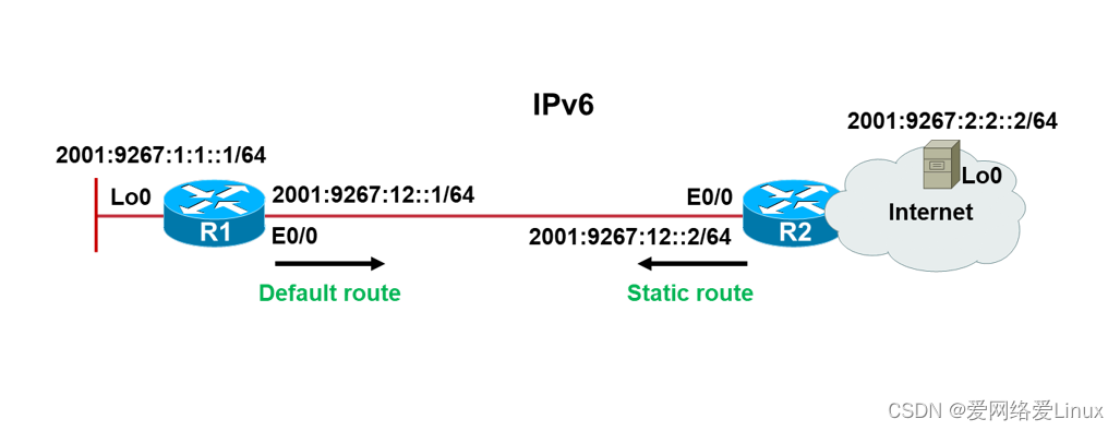
实验需求
- 根据实验拓扑图,完成设备的基本配置;
- 在R2上配置IPv6静态路由,使得R2能够访问R1的Loopback0;
- 在R1上配置IPv6默认路由,使得R1能够访问R2的Loopback0。
实验步骤
步骤1:设备的基本配置
配置R1:
Router>enable
Router#configure terminal
Router(config)#hostname R1
R1(config)#no ip domain-lookup
R1(config)#line console 0
R1(config-line)#exec-timeout 0 0
R1(config-line)#logging synchronous
R1(config-line)#exit
R1(config)#interface loopback 0
R1(config-if)#ipv6 address 2001:9267:1:1::1/64
R1(config-if)#exit
R1(config)#interface ethernet0/0
R1(config-if)#ipv6 address 2001:9267:12::1/64
R1(config-if)#no shutdown
R1(config-if)#end
R1#
配置R2:
Router>enable
Router#configure terminal
Router(config)#hostname R2
R2(config)#no ip domain-lookup
R2(config)#line console 0
R2(config-line)#exec-timeout 0 0
R2(config-line)#logging synchronous
R2(config-line)#exit
R2(config)#interface loopback 0
R2(config-if)#ipv6 address 2001:9267:2:2::2/64
R2(config-if)#exit
R2(config)#interface ethernet0/0
R2(config-if)#ipv6 address 2001:9267:12::2/64
R2(config-if)#no shutdown
R2(config-if)#end
R2#
步骤2:配置IPv6静态路由
配置R1:
R1(config)#ipv6 route ::/0 2001:9267:12::2
R1(config)#end
R1#
配置R2:
R2(config)#ipv6 route 2001:9267:1:1::/64 2001:9267:12::1
R2(config)#end
R2#
步骤3:检查IPv6静态路由
检查R1:
R1#show ipv6 route
IPv6 Routing Table - default - 6 entries
Codes: C - Connected, L - Local, S - Static, U - Per-user Static route
B - BGP, HA - Home Agent, MR - Mobile Router, R - RIP
H - NHRP, I1 - ISIS L1, I2 - ISIS L2, IA - ISIS interarea
IS - ISIS summary, D - EIGRP, EX - EIGRP external, NM - NEMO
ND - ND Default, NDp - ND Prefix, DCE - Destination, NDr - Redirect
RL - RPL, O - OSPF Intra, OI - OSPF Inter, OE1 - OSPF ext 1
OE2 - OSPF ext 2, ON1 - OSPF NSSA ext 1, ON2 - OSPF NSSA ext 2
la - LISP alt, lr - LISP site-registrations, ld - LISP dyn-eid
lA - LISP away, a - Application
S ::/0 [1/0]
via 2001:9267:12::2
C 2001:9267:1:1::/64 [0/0]
via Loopback0, directly connected
L 2001:9267:1:1::1/128 [0/0]
via Loopback0, receive
C 2001:9267:12::/64 [0/0]
via Ethernet0/0, directly connected
L 2001:9267:12::1/128 [0/0]
via Ethernet0/0, receive
L FF00::/8 [0/0]
via Null0, receive
检查R2:
R2#show ipv6 route
IPv6 Routing Table - default - 6 entries
Codes: C - Connected, L - Local, S - Static, U - Per-user Static route
B - BGP, HA - Home Agent, MR - Mobile Router, R - RIP
H - NHRP, I1 - ISIS L1, I2 - ISIS L2, IA - ISIS interarea
IS - ISIS summary, D - EIGRP, EX - EIGRP external, NM - NEMO
ND - ND Default, NDp - ND Prefix, DCE - Destination, NDr - Redirect
RL - RPL, O - OSPF Intra, OI - OSPF Inter, OE1 - OSPF ext 1
OE2 - OSPF ext 2, ON1 - OSPF NSSA ext 1, ON2 - OSPF NSSA ext 2
la - LISP alt, lr - LISP site-registrations, ld - LISP dyn-eid
lA - LISP away, a - Application
S 2001:9267:1:1::/64 [1/0]
via 2001:9267:12::1
C 2001:9267:2:2::/64 [0/0]
via Loopback0, directly connected
L 2001:9267:2:2::2/128 [0/0]
via Loopback0, receive
C 2001:9267:12::/64 [0/0]
via Ethernet0/0, directly connected
L 2001:9267:12::2/128 [0/0]
via Ethernet0/0, receive
L FF00::/8 [0/0]
via Null0, receive
步骤3:测试IPv6网络的连通性
测试R1:
R1#ping 2001:9267:2:2::2 source loopback 0
Type escape sequence to abort.
Sending 5, 100-byte ICMP Echos to 2001:9267:2:2::2, timeout is 2 seconds:
Packet sent with a source address of 2001:9267:1:1::1
!!!!!
Success rate is 100 percent (5/5), round-trip min/avg/max = 1/1/1 ms
联系我们


等级考试试卷(四级)真题,含答案解析)


服务搭建详解以及api集成和踩坑说明)


)


