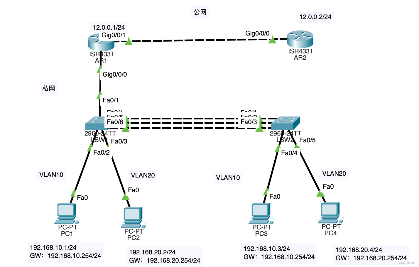
实验拓扑图:

实验目的:
- 如图所示配置相应IP地址和VLAN,并通过在AR1上配置单臂路由,实现VLAN10和VLAN20的主机能够在VLAN间通信;
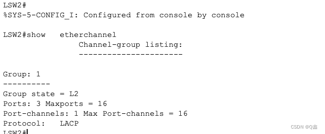
- 在SW1和SW2的三条链路实施链路聚合,使用静态LACP模式,使一条链路处于active,其他处于backup状态;
- 在AR1上配置NAT,实现192.168.10.0网段的主机可以ping通AR2
实验步骤:
实验目的一:如图所示配置相应IP地址和VLAN,并通过在AR1上配置单臂路由,实现VLAN10和VLAN20的主机能够在VLAN间通信;
1、LSW1上:
创建VLAN并将端口划入VLAN
Switch>en
Switch#conf t
Switch(config)#hostname LSW1
LSW1(config)#vl 10
LSW1(config-vlan)#vl 20
LSW1(config-vlan)#int f0/2
LSW1(config-if)#sw ac vlan 10
LSW1(config-if)#exit
LSW1(config)#int f0/3
LSW1(config-if)#sw ac vl 20
修改接口模式为trunk
LSW1(config-if)#int f0/1
LSW1(config-if)#sw mo tr
2、AR1上
给g0/0/1接口配置IP地址
Router>en
Router#conf t
Router(config)#hostname AR1
AR1(config)#int g0/0/1
AR1(config-if)#ip add 12.0.0.1 255.255.255.0
AR1(config-if)#no shut
AR1(config-if)#no shutdown
打开g0/0/0端口并配置子接口
AR1(config-if)#int g0/0/0
AR1(config-if)#no shutdown AR1(config-if)#int g0/0/0.1
AR1(config-subif)#encapsulation dot1Q 10
AR1(config-subif)#ip add 192.168.10.254 255.255.255.0
AR1(config-subif)#no shut
AR1(config-subif)#exitAR1(config)#int g0/0/0.2
AR1(config-subif)#encapsulation dot1Q 20
AR1(config-subif)#ip add 192.168.20.254 255.255.255.0
AR1(config-subif)#no shut
AR1(config-subif)#exit
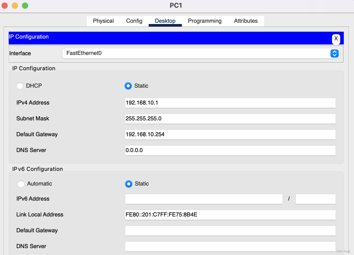
给各PC配置IP、网关(以PC1为例)

3、测试:
PC1与PC2互通

实验目的二:在SW1和SW2的三条链路实施链路聚合,使用静态LACP模式,使一条链路处于active,其他处于backup状态;
1、LSW2上:
配置VLAN,将接口划入VLAN
Switch>en
Switch#conf t
Switch(config)#hostname LSW2
LSW2(config)#vl 10
LSW2(config-vlan)#vl 20
LSW2(config-vlan)#int f0/4
LSW2(config-if)#sw ac vl 10
LSW2(config-if)#no shut
LSW2(config-if)#int f0/5
LSW2(config-if)#sw ac vl 20
LSW2(config-if)#no shut
配置lacp链路聚合
LSW2(config)#int range f0/1-3
LSW2(config-if-range)#channel-protocol lacp
LSW2(config-if-range)#channel-group 1 mode active
2、LSW1上:
配置lacp链路聚合
LSW1(config)#int range f0/4-6
LSW1(config-if-range)#channel-protocol lacp
LSW1(config-if-range)#channel-group 1 mode active

实验目的三:在AR1上配置NAT,实现192.168.10.0网段的主机可以ping通AR2
1、配置AR2
Router>en
Router#conf t
Router(config)#hostname AR2
AR2(config)#int g0/0/0
AR2(config-if)#ip add 12.0.0.2 255.255.255.0
AR2(config-if)#no shut
2、在AR1上做NAT
AR1(config)#access-list 1 permit 192.168.0.0 0.0.255.255
AR1(config)#ip nat pool qyx12.0.0.3 12.0.0.4 netmask 255.255.255.0
AR1(config)#ip nat inside source list 1 pool qyx overload
绑定虚拟子接口:
AR1(config)#int g0/0/0.1
AR1(config-subif)#encapsulation dot1Q 10
AR1(config-subif)#ip nat inside
AR1(config-subif)#int g0/0/0.2
AR1(config-subif)#encapsulation dot1Q 20
AR1(config-subif)#ip nat inside
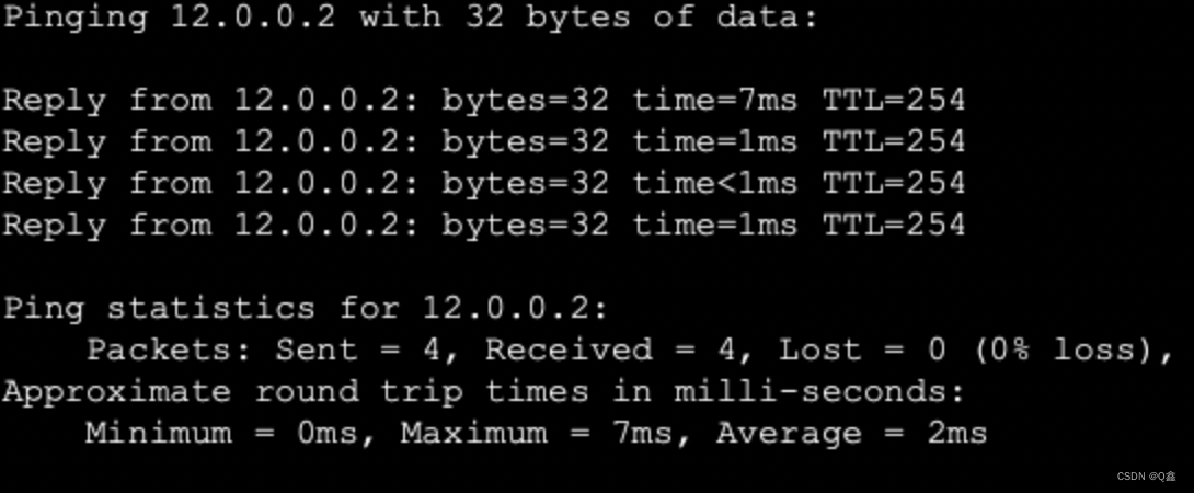
私网能访问公网
PC1访问AR2


(10)----读取DHT11温湿度数据)


)
的结合思考)
)
