前言:
前面分享过不同note CA 技术文档
这里主要参考 4G|ShareTechnote 《Carrier Aggregation》
CA SCell 添加的小区的流程:
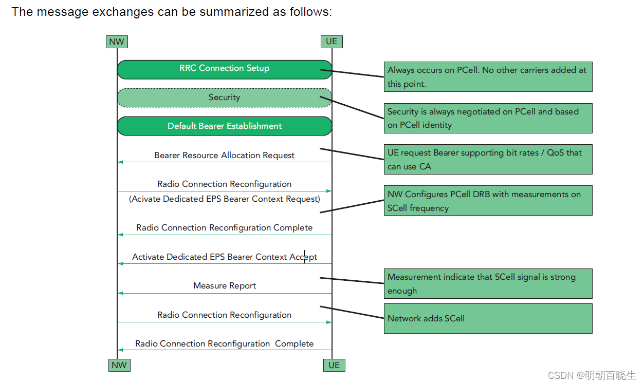
SCell addition and removal:
1 The carrier aggregation additional SCells cannot be activated immediately at the time of RRC establishment. Thus,there is no provision in the RRC Connection Setup procedure for SCells. SCells are added and removed from the set of serving cells through the RRC Connection Reconfiguration procedure.Note that, since intra-LTE handover is treated as an RRC connection reconfiguration, SCell “handover” is supported.The CA-related information sent by the base station pursuant to this the RRC Connection Reconfiguration procedure is summarized below :
• Cross-carrier scheduling configuration – Indicates, among other things, if scheduling for the referenced SCell is handled by that SCell or by another cell.
• SCell PUSCH configuration – Indicates, among other things, whether resource block group hopping is utilized on the SCell.
• SCell uplink power control configuration – Carries a number of primitives related to SCell uplink TPC,including the path loss reference linking parameter.
• SCell CQI reporting configuration – Carries a number of primitives related to CQI measurements reporting for SCells.
目录:
- Initial Motivation for Carrier Aggregation
- Initial Deployment
- Overview of Carrier Allocation and Network Architecture
- Layer 2 Structure of Carrier Aggregation
- What kind of Aggregated Carrier (Carrier Combination) is possible ?
- Determining Channel Spacing for Intraband Contiguous CA
- How a Network know if a UE support Carrier Aggregation ?
- Overall Sequence of Adding a Second Carrier
- Evolution path of Carrier Aggregation / Possible Test Plan
E-UTRA CA configurations and bandwidth combination sets defined for intra-band contiguous CA
E-UTRA CA configurations and bandwidth combination sets defined for non-contiguous intra-band CA (with two sub-blocks)
E-UTRA CA configurations and bandwidth combination sets defined for inter-band CA
Test Frequency Table
一 Initial Motivation for Carrier Aggregation
尽管目前的LTE最大支持20Mhz BW,但只有少数网络运营商获得了如此宽带宽的认证。网络运营商对LTE最常见的带宽是10MHz,这意味着他们在带宽方面没有充分利用LTE能力。这不是因为技术限制,纯粹是因为分配带宽的许可问题。
尽管没有多少网络运营商具有20Mhz BW,但也有一些网络运营商拥有多频带许可证(例如,两个分离的10Mhz BW和两个或更多5Mhz BW)。这些网络运营商希望将这些多个频带组合以实现宽BW(在大多数情况下为20Mhz BW)LTE。这是目前LTE-Advanced的最初动机。
充分利用离散的频谱资源,增加带宽,提高吞吐量。
二 Initial Deployment
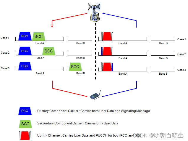
PCell 和 SCell 传输什么类型的数据,根据上下行情况如下
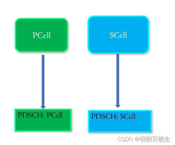
2.1 DL PDSCH
PCell & SCell 独立传输 PDSCH 数据
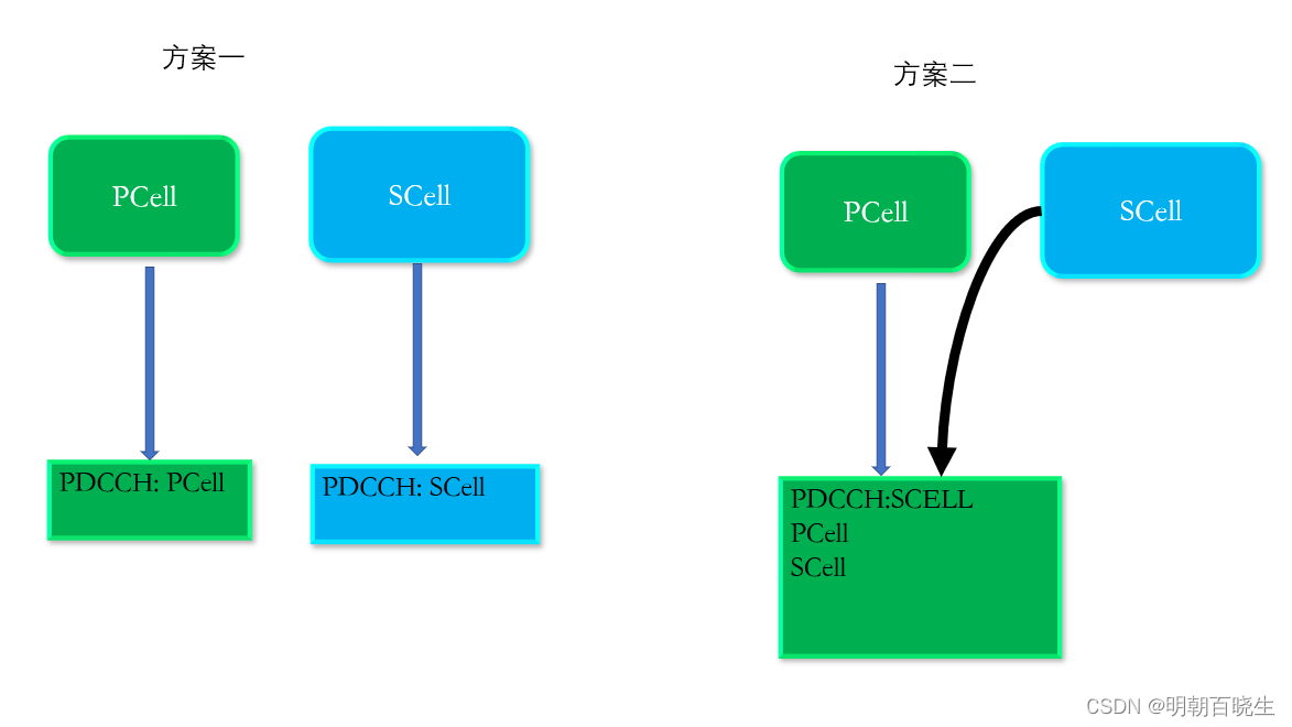
2.2 DL PDCCH
两种方案:
方案一: 独立映射,SCell 需要侦听对应SCell 的PDCCH
方案二: SCell的PDCCH 放在PCell 的PDCCH 里面,通过CIF 区分开,
在CRS 方案里面用到,正常不用
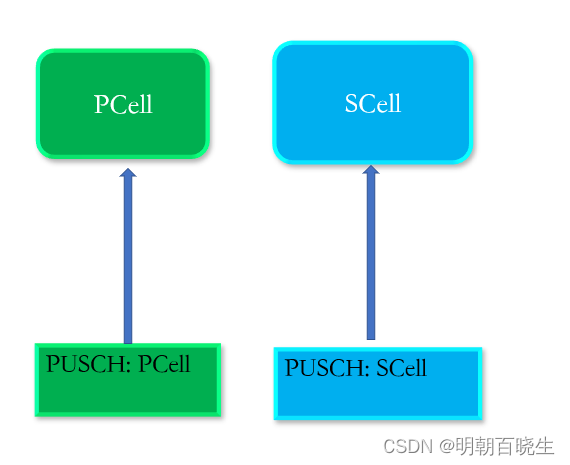
2.3 UL PUSCH
How kind of data you would carry on UL carrier
There would be no differences in terms of PUSCH,
独立传输
2.4 UL PUCCH
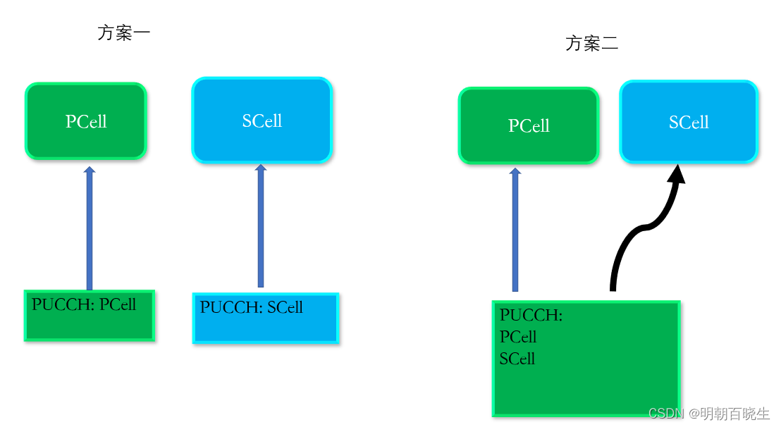
but how about PUCCH? Since UE is getting PDSCHs from two separate carriers, there should be questions of how to send HARQ ACK/NACK for each of the PDSCH. Should UE send separate PUCCHs(HARQ ACK/NACK for each DL carriers) or single PUCCH carrying the HARQ ACK/NACK for both channels. Both options are possible in terms of Rel 9/Rel 10 specification, but it is higher possibility to use a single PUCCH for carrying HARQ ACK/NACK for both DL carriers.
MAC 层收到PDSCH 内容,需要通过PUCCHs 反馈 HARQ ACK|NACK,
两种方案: 一种独立的,一种放在一个CA 反馈 HARQ
2.5 PRACH
- PRACH via Primary Carrier and RAR via Primary Carrier
- PRACH via Primary Carrier and RAR via Secondary Carrier
- PRACH via Secondary and RAR via Secondary Carrier
- and couple of others.
在NSA 里面, RAR 是独立的.
三 Overview of Carrier Allocation and Network Architecture
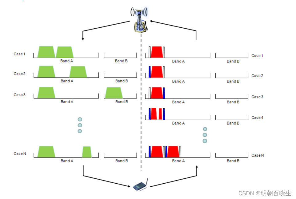
如下: 左边是下行,右边是上行。
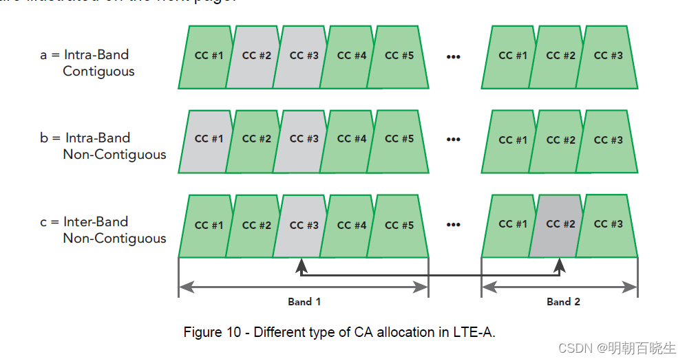
CA 有三种类型:
Intra-band Contiguous
Intra-Band Non-Contiguous
Inter-Band Non-Contiguous
则网络也是按照如下分配,部署无线资源。针对上行 支持 Intra-band 类型
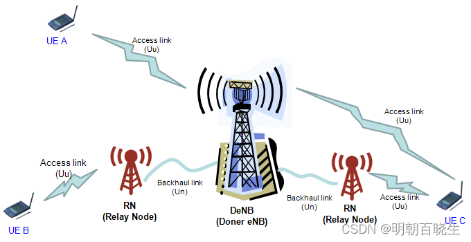
 LTE-Advanced的另一个方面是网络架构方面。高级LTE的一个关键修改是“中继节点”,以改善数据通信,特别是在小区边界上,并增加小区覆盖范围
四 Layer 2 Structure of Carrier Aggregation
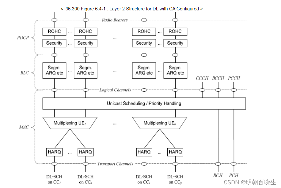
载波层聚合是MAC-PHY层的概念,它不适用于更高层
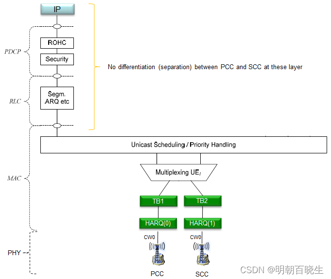
4.1 SISO CA 路径
为了清楚起见,我们假设一个载波聚合的情况,其中有2个CC(分量载波),并且每个载波都支持SISO。以下是从IP到物理层的全部数据路径。正如您所看到的,从IP到RLC,PCC和SCC之间没有单独的路径。
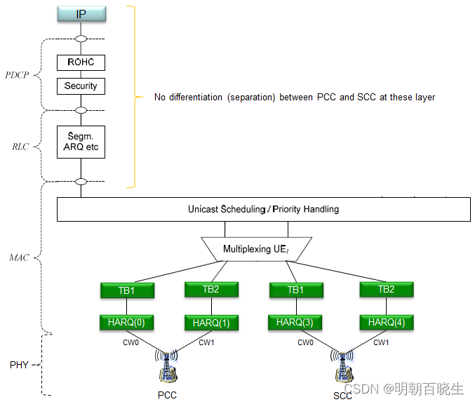
4.2 MIMO CA 路径
为了清楚起见,让我们假设具有2CC(分量载波)的载波聚合的情况,并且每个载波支持MIMO。以下是从IP到物理层的总体数据路径。正如您所看到的,从IP到RLC,PCC和SCC之间没有单独的路径。
五 What kind of Aggregated Carrier (Carrier Combination) is possible ?
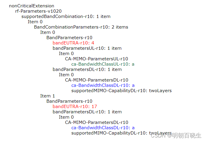
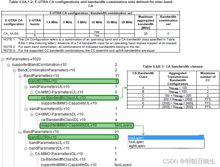
通过 [0xB0C0] UL_DCCH / UECapabilityInformation OTA 可以看到

bandCombinationListEUTRA:
一个条目对应于supportedBandCombination中相同的顺序列出的每个支持的波段组合。
BandCombinationParameters-v1090:
如果包括,UE应包括与BandCombination Parameters-r10中相同数量的条目,并按相同顺序列出。
BandCombinationParameters-v1130:
该字段适用于每个支持的CA带宽类别组合(即TS 36.101第5.6A.1节中相应频带组合中指示的CA配置
有的Band 同时支持上行CA,有的只支持下行CA,同时MIMO 情况也不一样
UE能力信息中的载波组合信息的一个示例如下:
该示例示出了UE允许Band4和Band17之间的载波聚合。
CA 聚合类型如下
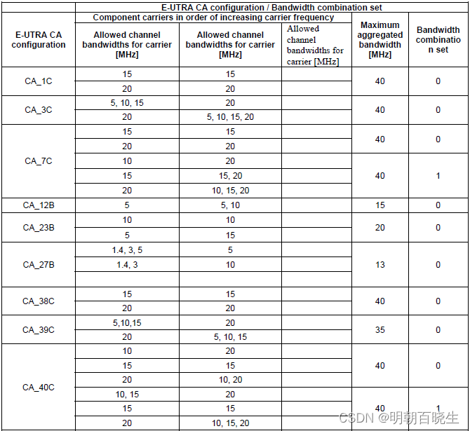
36.101 Table 5.6A.1-3: E-UTRA CA configurations and bandwidth combination sets defined for non-contiguous intra-band CA (with two sub-blocks) >
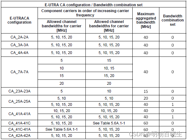
36.101 Table 5.6A.1-2: E-UTRA CA configurations and bandwidth combination sets defined for inter-band CA
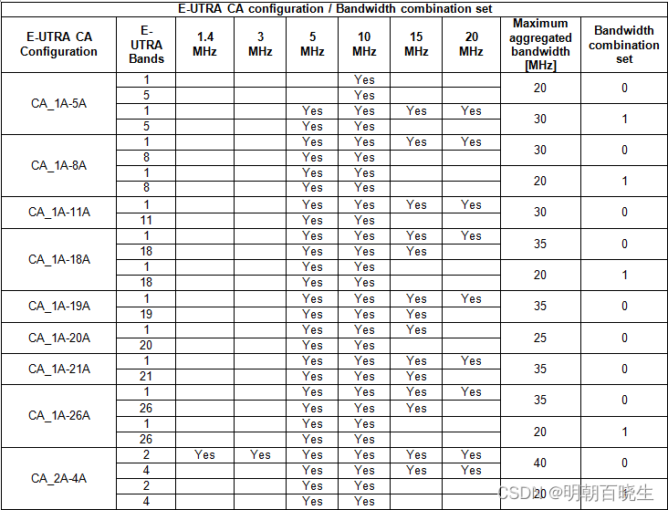
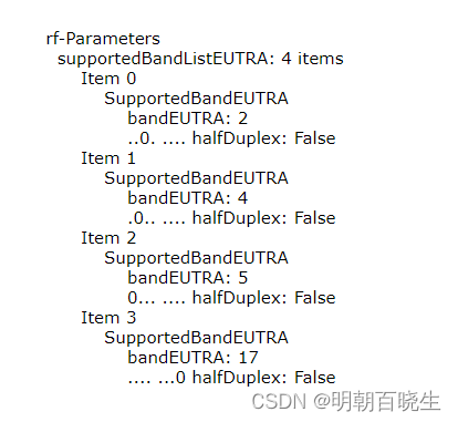
One of the UE capability information that may confuses you would be following IE. This IE shows you which band are supported by the UE in terms of single carrier. It is not about Carrier Aggregation.(跟CA 无关,只代表UE 支持Band 情况)
六 Determining Channel Spacing for Intraband Contiguous CA
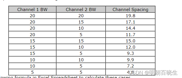
在Contiguous CA情况下,计算出两个 channel 之间的 channel spacing并不容易,
因为没有guardband . 这种spacing between 两个intraband contiguous CA band 可以通过
下面等式计算 36.521-1 5.4.1A

Based on this equation, I've calculated following cases.
< 36.508 - Table 4.3.1.1.1A-1: Test frequencies for CA_1C >
< 36.508 - Table 4.3.1.1.1A-1: Test frequencies for CA_1C >

< 36.508 - Table 4.3.1.1.3A-1: Test frequencies for CA_3C >
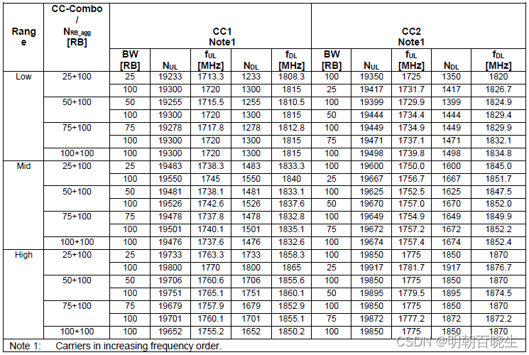
< 36.508 - Table 4.3.1.1.7A-1: Test frequencies for CA_7C >
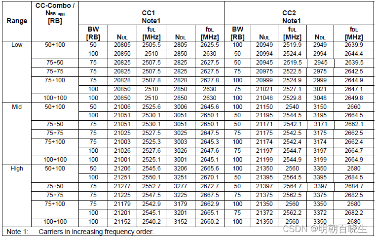
< 36.508 - Table 4.3.1.2.6A-1: Test frequencies for CA_38C >
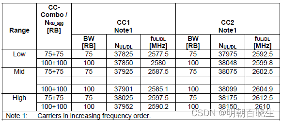
< 36.508 - Table 4.3.1.2.7A-1: Test frequencies for CA_39C >
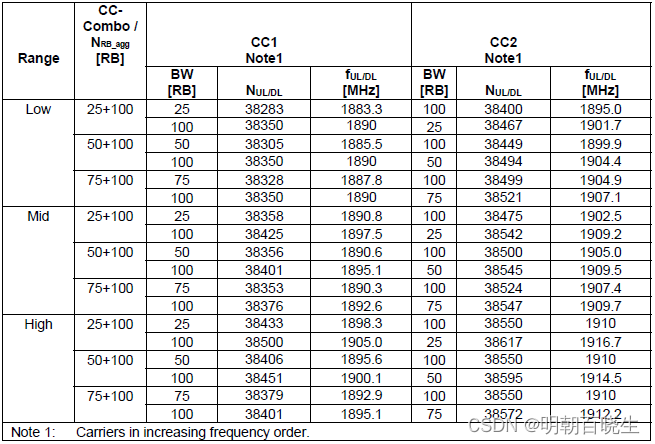
< 36.508 - Table 4.3.1.2.8A-1: Test frequencies for CA_40C >
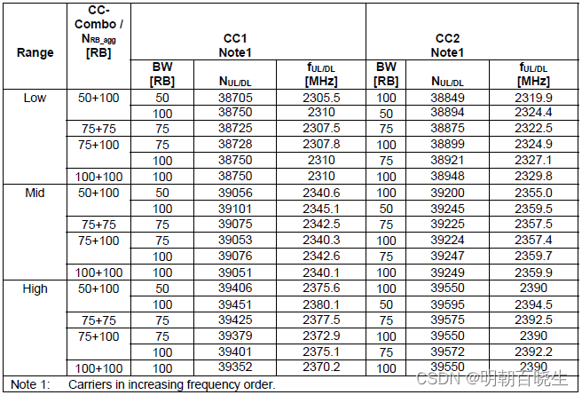
< 36.508 - Table 4.3.1.2.9A-1: Test frequencies for CA_41C >
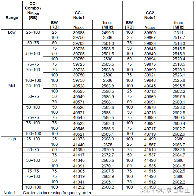
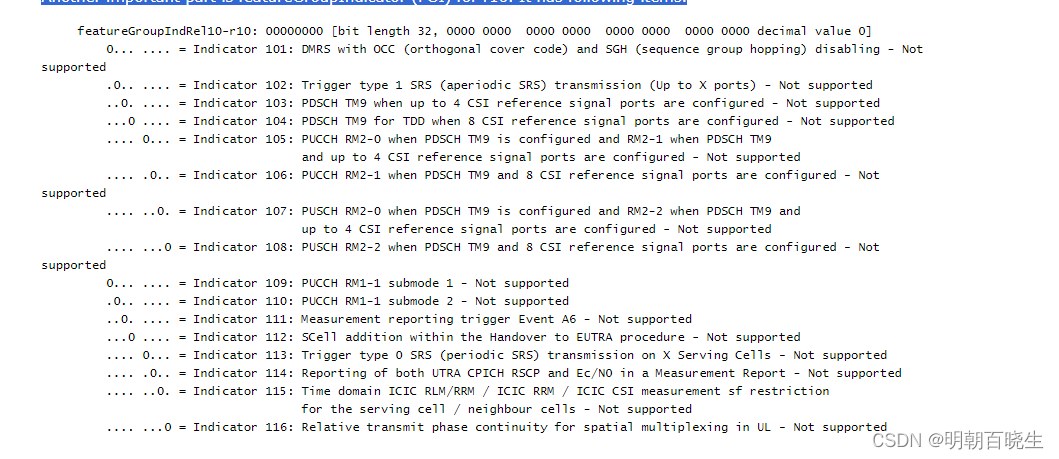
七 How a Network know if a UE support Carrier Aggregation ?
Another important part is featureGroupIndicator (FGI) for r10. It has following items.
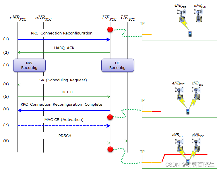
八 Overall Sequence of Adding a Second Carrier
九 Evolution path of Carrier Aggregation / Possible Test Plan
- 2 CC Aggregation - SISO, Cat 3, PUSCH enabled : HARQ Ack/Nack is carried by PUSCH
- 2 CC Aggregation - SISO, Cat 3, PUSCH diabled : HARQ Ack/Nack is carried by PUCCH Format 1b
- 2 CC Aggregation - SISO with CSI Report - Periodic
- 2 CC Aggregation - SISO with CSI Report - Aperiodic
- 2 CC Aggregation - SISO, Handover for SCC Change
- 2 CC Aggregation - SISO, Handover for PCC Change
- 2 CC Aggregation - SISO, Handover for both SCC and PCC Change
- 2 CC Aggregation - 2x2 MIMO, Cat 3, PUSCH enabled : HARQ Ack/Nack is carried by PUSCH
- 2 CC Aggregation - 2x2 MIMO, Cat 3, PUSCH diabled : HARQ Ack/Nack is carried by PUCCH Format 1b
- 2 CC Aggregation - 2x2 MIMO, Cat 3, 40 Mhz Aggregated BandWidth, 200 Mbps Throughput at IP layer
- 2 CC Aggregation - SISO, Cat 4, PUSCH enabled : HARQ Ack/Nack is carried by PUSCH
- 2 CC Aggregation - SISO, Cat 4, PUSCH diabled : HARQ Ack/Nack is carried by PUCCH Format 1b
- 2 CC Aggregation - 2x2 MIMO, Cat 6, MIMO, 20 Mhz Aggregated Bandwidth, 150 Mbps Throughput at IP layer
- 2 CC Aggregation - 2x2 MIMO, Cat 6, MIMO, 40 Mhz Aggregated Bandwidth, 300 Mbps Throughput at IP layer
- 2 CC Aggregation - TM 8
- 2 CC Aggregation - TM 9
- 3 CC Aggregation - SISO, Cat 6, 30 Mhz Aggregated BW, PUSCH enabled : HARQ Ack/Nack is carried by PUSCH
- 3 CC Aggregation - SISO, Cat 6, 30 Mhz Aggregated BW,PUSCH diabled : HARQ Ack/Nack is carried by PUCCH Format 3
- 3 CC Aggregation - 2x2 MIMO, Cat 6, 30 Mhz Aggregated BW, PUSCH enabled : HARQ Ack/Nack is carried by PUSCH
- 3 CC Aggregation - 2x2 MIMO, Cat 6, 30 Mhz Aggregated BW, PUSCH diabled : HARQ Ack/Nack is carried by PUCCH Format 3
- 3 CC Aggregation - 2x2 MIMO, Cat 6, 40 Mhz Aggregated BW
- 3 CC Aggregation - 2x2 MIMO, Cat 6, 60 Mhz Aggregated BW
- 3 CC Aggregation - 4x4,4x4,4x2 Cat 16, 60 Mhz Aggregated BW
- 4 CC Aggregation - All 2x2, 80 Mhz Aggregated BW
- 5 CC Aggregation - All 2x2, 100 Mhz Aggregated BW
- 5 CC Aggregation - All 4x4, 100 Mhz Aggregated BW
十一 Activation/Deactivation of Secondary Cell
A typical use case of Activation of the SCell would that the network configures the UE with
one or more component carriers (CCs) but deactivate all of them except the Primary CC.
When there is a need of more data throughput (for example, there is a huge amount of
data to delivered to the UE in the downlink), the network can activate several
secondary CCs to maximize downlink throughput.
Another use case could be that if the PCell is fully loaded, the SCell can be activated and
the data transfer can be scheduled only on the SCell (Load balancing).
The network can deactivate the SCell when there is no more data to be delivered to the
UE or the channel quality of the SCell turning to be bad.
The UE (and the network) can deactivate the activated SCell without explicit signaling
which is based on sCellDeactivationTimer. This is the amount of time (in radio frames)
the UE has not received any data on the SCell.
SCell Activation is done via MAC Control Element whereas the deactivation mechanism is
either by using MAC control element or by the expiry of the sCellDeactivationTimer.
The Activation/Deactivation MAC control element is identified by a MAC PDU subheader
with unique LCID: 11011. It has a fixed size and consists of a single octet containing seven
C-fields and one R-field (Reserved bit and is set to “0”). Each C-field represents an SCell
with SCellIndex which ranges from 1-7.
The MAC control element carries a bitmap for the activation and deactivation of SCells:
set to 1 denotes activation of the corresponding SCell, while a bit set to 0 denotes
deactivation.
With the bitmap, SCells can be activated and deactivated individually, and a single
activation/deactivation command can activate/deactivate a subset of the SCells.
The Activation/Deactivation MAC CE and its subheader are illustrated in the below Figure.

If the UE receives an Activation/Deactivation MAC CE in subframe #n activating the SCell,
the UE shall apply the below defined actions no earlier than subframe #n+8 and no later
than subframe #n+24 or subframe #n+34 (as defined in section 7.7.2 of 36.133)
― Transmit SRS on the SCell in case if UL CA and SRS on the SCell is configured;
― PDCCH monitoring on the SCell;
― PDCCH monitoring for the SCell (Cross Carrier Scheduling);
― CSI reporting for the SCell. The UE should start transmitting valid CSI report no later
than subframe #n+24 or #n+34 (as defined in section 7.7.2 of 36.133) but it can report out
of range (CQI index = 0) values from subframe #n+8, otherwise the eNodeB have
to perform blind decoding of PUSCH (if scheduled) from subframe #n+8 till subframe
#n+24 or #n+34
If the SCell is deactivated, the UE shall apply the following activations:
If the SCell is deactivated, the UE shall apply the following activations:
― SRS shall not be transmitted in case if UL CA and SRS on the SCell is configured
― The UE shall not transmit UL-SCH on the SCell (UL CA)
― PDCCH on/for the SCell shall not be monitored.
― The UE shall flush all HARQ buffers associated with the SCell.
― The UE shall not transmit RACH on the SCell (Introduced in Release-11, and the RA
procedure on an SCell shall only be initiated by a PDCCH order). When SCell is
deactivated, the ongoing RA procedure on the SCell, if any, is aborted
― The UE shall stop reporting CSI from subframe #n+8 if the sCellDeactivationTimer
associated with the SCell expires in subframe #n or if the UE receives an
Activation/Deactivation MAC CE in subframe #n deactivating the SCell
: BGP原理与配置)


实现计算器UI界面(三))


)
)


)
