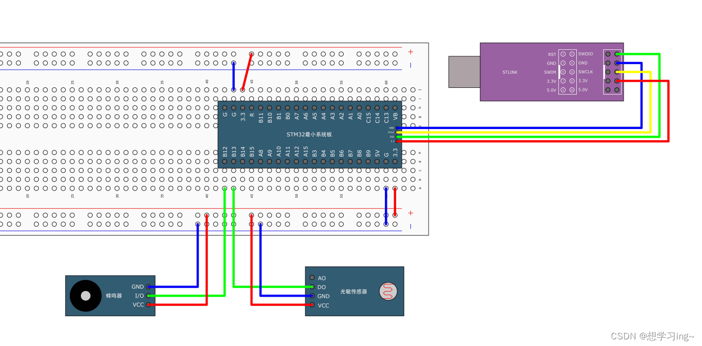
接线

GPIO配置
初始化GPIO
1.使用RCC开启GPIO时钟
void RCC_APB2PeriphClockCmd(uint32_t RCC_APB2Periph, FunctionalState NewState);
作用:外设时钟控制(根据外设连接的总线选择要开启的时钟)
RCC_AHBPeriph/RCC_APB2Periph/RCC_APB1Periph:选择外设
NewState:使能/使能
2.使用GPIO_Init初始化GPIO
void GPIO_Init(GPIO_TypeDef* GPIOx, GPIO_InitTypeDef* GPIO_InitStruct);
作用:用结构体的参数初始化GPIO。
用法:先定义一个结构体变量,再给变量赋值,最后调用这个函数即可(这个函数就会自动读取结构体的值,然后自动把外设的各个参数配置好)。
原文链接:https://blog.csdn.net/m0_74246768/article/details/139132178
上面初始化的配置上一篇有写过,需要的同学可以看一下上一篇的库函数。
点亮LED
LED:发光二极管,正向通电点亮,反向通电不亮
void GPIO_SetBits(GPIO_TypeDef* GPIOx, uint16_t GPIO_Pin);
作用:把指定的端口设置为高电平
熄灭LED
void GPIO_ResetBits(GPIO_TypeDef* GPIOx, uint16_t GPIO_Pin);
作用:把指定的端口设置为低电平
LED.c
#include "stm32f10x.h"                  // Device headervoid LED_Init(void)
{RCC_APB2PeriphClockCmd(RCC_APB2Periph_GPIOA, ENABLE);GPIO_InitTypeDef GPIO_InitStructure;GPIO_InitStructure.GPIO_Mode = GPIO_Mode_Out_PP;GPIO_InitStructure.GPIO_Pin = GPIO_Pin_1 | GPIO_Pin_2;GPIO_InitStructure.GPIO_Speed = GPIO_Speed_50MHz;GPIO_Init(GPIOA, &GPIO_InitStructure);GPIO_SetBits(GPIOA, GPIO_Pin_1 | GPIO_Pin_2);
}void LED1_ON(void)
{GPIO_ResetBits(GPIOA, GPIO_Pin_1);
}void LED1_OFF(void)
{GPIO_SetBits(GPIOA, GPIO_Pin_1);
}void LED1_Turn(void)
{if (GPIO_ReadOutputDataBit(GPIOA, GPIO_Pin_1) == 0){GPIO_SetBits(GPIOA, GPIO_Pin_1);}else{GPIO_ResetBits(GPIOA, GPIO_Pin_1);}
}void LED2_ON(void)
{GPIO_ResetBits(GPIOA, GPIO_Pin_2);
}void LED2_OFF(void)
{GPIO_SetBits(GPIOA, GPIO_Pin_2);
}void LED2_Turn(void)
{if (GPIO_ReadOutputDataBit(GPIOA, GPIO_Pin_2) == 0){GPIO_SetBits(GPIOA, GPIO_Pin_2);}else{GPIO_ResetBits(GPIOA, GPIO_Pin_2);}
}
LED.h
#ifndef __LED_H
#define __LED_Hvoid LED_Init(void);
void LED1_ON(void);
void LED1_OFF(void);
void LED1_Turn(void);
void LED2_ON(void);
void LED2_OFF(void);
void LED2_Turn(void);#endif
蜂鸣器配置
思路:给蜂鸣器输出低电平,蜂鸣器响;输出高电平,蜂鸣器不响。(蜂鸣器接到了PB12)
初始化配置:初始化GPIO口即可。
响和不响就是根据置高电平和低电平决定。与LED电量和熄灭一样。
Buzzer.c
#include "stm32f10x.h"                  // Device headervoid Buzzer_Init(void)
{RCC_APB2PeriphClockCmd(RCC_APB2Periph_GPIOB, ENABLE);GPIO_InitTypeDef GPIO_InitStructure;GPIO_InitStructure.GPIO_Mode = GPIO_Mode_Out_PP;GPIO_InitStructure.GPIO_Pin = GPIO_Pin_12;GPIO_InitStructure.GPIO_Speed = GPIO_Speed_50MHz;GPIO_Init(GPIOB, &GPIO_InitStructure);GPIO_SetBits(GPIOB, GPIO_Pin_12);
}void Buzzer_ON(void)
{GPIO_ResetBits(GPIOB, GPIO_Pin_12);
}void Buzzer_OFF(void)
{GPIO_SetBits(GPIOB, GPIO_Pin_12);
}void Buzzer_Turn(void)
{if (GPIO_ReadOutputDataBit(GPIOB, GPIO_Pin_12) == 0){GPIO_SetBits(GPIOB, GPIO_Pin_12);}else{GPIO_ResetBits(GPIOB, GPIO_Pin_12);}
}
Buzzer.h
#ifndef __BUZZER_H
#define __BUZZER_Hvoid Buzzer_Init(void);
void Buzzer_ON(void);
void Buzzer_OFF(void);
void Buzzer_Turn(void);#endif
光敏传感器模块
思路:光敏传感器挡住光时给PB13置1,不挡住时为0;
可通过GPIO的读取函数读取PB13的值。
uint8_t GPIO_ReadInputDataBit(GPIO_TypeDef* GPIOx, uint16_t GPIO_Pin);
uint16_t GPIO_ReadInputData(GPIO_TypeDef* GPIOx);
uint8_t GPIO_ReadOutputDataBit(GPIO_TypeDef* GPIOx, uint16_t GPIO_Pin);
uint16_t GPIO_ReadOutputData(GPIO_TypeDef* GPIOx);
作用:GPIO的读取函数(GPIO的输入函数)
LightSensor.c
#include "stm32f10x.h"                  // Device headervoid LightSensor_Init(void)
{RCC_APB2PeriphClockCmd(RCC_APB2Periph_GPIOB, ENABLE);GPIO_InitTypeDef GPIO_InitStructure;GPIO_InitStructure.GPIO_Mode = GPIO_Mode_IPU;GPIO_InitStructure.GPIO_Pin = GPIO_Pin_13;GPIO_InitStructure.GPIO_Speed = GPIO_Speed_50MHz;GPIO_Init(GPIOB, &GPIO_InitStructure);
}uint8_t LightSensor_Get(void)
{return GPIO_ReadInputDataBit(GPIOB, GPIO_Pin_13);
}
LightSensor.h
#ifndef __LIGHT_SENSOR_H
#define __LIGHT_SENSOR_Hvoid LightSensor_Init(void);
uint8_t LightSensor_Get(void);#endif
例题:光敏传感器控制蜂鸣器
遮住光敏电阻,蜂鸣器响;
#include "stm32f10x.h"                  // Device header
#include "Delay.h"
#include "Buzzer.h"
#include "LightSensor.h"int main(void)
{Buzzer_Init();LightSensor_Init();while (1){if (LightSensor_Get() == 1){Buzzer_ON();}else{Buzzer_OFF();}}
}
有什么不对的地方可以评论区里提出来,欢迎一起学习。

详细介绍)
)
)


下安装mysql5.7)

)


的开发框架)